Last time, I gave you an overview of what you get from I2C, basics like addressing, interface speeds, and a breakdown of pullups. Today, let’s continue looking into I2C capabilities and requirements – level shifting, transfer types, and quirks like combined transfers or clock stretching.
Level Shifting
Today, the overwhelming majority of I2C devices are 3.3 V logic. but this wasn’t always the case. If you work with old tech or with I2C on VGA/DVI/HDMI ports, you will see 5 V I2C networks, and if you work with very new tech, you will see 1.8 V I2C networks; rarely, you might even see 2.5 V networks!
Interfacing 5 V devices with a 3. 3V controller, it might not be necessary to level shift. You need to a) wire pullups to 3.3 V, and b) win the device input tolerance lottery. Same goes interfacing 3.3 V devices with 1.8 V hosts – wire up pullups to 1.8 V and pray to the stars. It can work in production – here’s Adafruit taking the 3.3 V-pulled-up Raspberry Pi I2C bus, and connecting it to a 5 V-powered MCP23017 chip that drives a 5 V-connected HD44780 display.
If your arrangement is different, or you’re experiencing a problem, you will want a level shifter circuit. At their simplest, two N-FETs like 2N7002 will do wonders. If you want smaller PCB footprint, better parameters, or more channels, there are level shifter chips, with many of them wonderfully suited for I2C (read the datasheet!). As we’ve featured before, some shifter ICs are too smart for their own good, while others will do just fine – if in doubt, remember to use your logic analyzer judiciously.
Two Ways To Talk
There are two kinds of I2C transfers you could expect to perform – I’d call them “simple transfers” and “register transfers”. With simple transfers, you send an address, and after the device ACKs, you either send or receive a single byte – it’s just like working with a shift register. With register transfers, you send an address, then a register number, and the device sends you the “contents” of that register – it’s more like working with an SPI display.
The PCF8574 is an I2C GPIO expander that does simple transfers. It has eight GPIO pins, and it only does simple transfers. How does that work, given it does both input and output? Well, the PCF8574 has only three possible states for all pin, with two of them combined together. The “Low” state (writing 0) is a hard pull down to GND. The “High” state (writing 1) is a weak pull to VCC – which also makes the pin work as an input with a pullup enabled. To check the input state, just read the expander state, and see if any of the pins you’ve set to 1 are now reading as 0. You can’t do a lot of high-side driving, sure, but you can still drive LEDs and check buttons, plus, this scheme is dead simple and covers a ton of use cases.
A good few I2C devices use simple transfers – the LM75 temperature sensor, for instance, only has to return temperature. You can read out multiple bytes at once, of course – simple transfers aren’t inherently limited to a single byte! PCF8575, the 16-bit sister of the PCF8574, has 16 GPIOs, I’ve used simple transfers with an ATMega328P keypard controller I created at some point – it would return keycodes, taken from a ring buffer. However, at some point, I decided to add more features to it, like ADC reading to help out a Pi Zero it was connected to, and had to upgrade it to register transfers.
The MCP23017 is a GPIO expander that uses register transfers. It has 16 GPIO pins, and a ton of features, each with their own register. Since one register contains 8 bits and we have 16 GPIOs, there are two registers per feature, and as such, there are two registers for pin directions, two for enabling integrated pullups, two for reading out input states, two for setting pins as outputs, and so on. They can even be arranged in two different ways, one backwards compatible with a different chip, by changing a bit in the status register! It’s a fair bit more complex chip than the PCF8574, but the complexity pays off where you need it.
I2C EEPROMs work with register transfers, too – some use 8-bit addresses, which allows for up to 256 bytes of storage. Higher-capacity EEPROMs use 16-bit (two-byte) addresses, where you’re expected to send in two bytes before you can read data out; if you try to read from such an EEPROM using two-byte addresses, you will just read back zeroes, so beware!
Quirks
But what if the device can’t keep up with the multi-byte transactions that your microcontroller is asking for? Maybe you have an EEPROM that needs time before it can read out a value from its internal memory so that it your MCU can receive it, maybe it’s a sensor that needs to average some values quickly and it just can’t catch up with even the lax timing requirements of 100 kHz I2C.
There’s a solution – it’s called clock stretching, and it’s basically an I2C device holding SCL low after receiving a byte, extending ACK state for a long time, until it can actually return meaningful data. As long as SCL is low, the controller should wait for the device. It’s essentially a way for a device to say “wait, not yet, I need some time before I can give you what you’re looking for”.
Raspberry Pi didn’t support clock stretching for the longest time due to a silicon bug. Every single Pi version before Pi 4 couldn’t handle clock stretching, including all of the Pi Zero versions released at the time of writing this article. The workaround, if you need one – use software I2C. It consumes more CPU since you have to use a kernel driver that bitbangs the bus, but it does have functional clock stretching. And of course the Raspberry Pi isn’t alone: if you are likely to need clock stretching, make sure that the microcontroller hardware peripheral supports it properly.
Next time, we dive into the physical layer, look at logic analyzer traces, understand how communication happens, and the ways it can break despite our best intentions.


The first time I had to deal with clock stretching was when I was interfacing knoxkoff wii nunchuck controllers with a PIC microcontroller.
It took me a while to realize the problem and after that I was shocked at the way clock stretching is often disregarded
always bitbang i2c, there is no bug free i2p hw out there.
Nah. It’s about tradeoffs – for instance, I have a Pi Zero (BCM2835) project where I’m using the hardware I2C peripheral to talk with an OLED screen (400KHz, doesn’t need clock stretching), and a software I2C driver to talk with a microcontroller (which likes clock stretching). Were I to use software I2C for both, I’d have userspace lagging constantly, since bitbanging, at its core, requires a non-negligible portion of CPU to do its work once you start to use a decent amount of bandwidth like a screen would.
You should also make the difference between bit-banging I2C Host and I2C Device- basically, you can’t bit-bang an I2C device and have it be in spec- (IIRC) in a transfer from the I2C device, you can very easily miss a “stop” from the host- start/stop are the only times that SDA is allowed to transition when SCL is high. Stop is SCL high and then SDA high, and without some detection hardware in the loop, very hard to “always” catch it.
Since I2C is not really a “stream” device- typically, the data is buffered and then considered delivered when it gets a “stop.”
There is (was?) a bug in the LM75 (a very basic hardware based state machine)- if you did an 8 bit read from a 16 bit register and the host didn’t “NAK” the byte, and the next bit in the 16 bit register is low, the SCL is held low by the LM75, so the the stop can’t be issued. Yes, there is a cascade of issues, but as I recall, this is part of the reason that follow-on specs raised the “minimum SCL” frequency from 0- basically allow a timeout.
oh that is a pretty good point, I’ll include that into the next article, which will go more in depth of the protocol’s inner workings! also, fun stuff about the LM75, didn’t know!
I have never had an issue that bad that I have had to bitbang I2C. Why waste processing power and potentially affect timing of other tasks if you don’t have to?
Lack of clock stretching is not a bug- clock stretching is definitely marked as “Optional” in the I2C spec.
lack of clock stretching by itself is not a bug, the problem was – it was meant to be implemented in silicon, but didn’t work due to a silicon bug in the IO!
It was meant to, yes. But the spec did not require it- and in silicon land, that usually gets written up in the errata first, and then incorporated into the datasheet as “feature!”
A very annoying point is the confusion that’s being spread around the usage of the device address.
For some reason the Arduino community embraces the 7-bit concept. And although the device address seems like 7 bits, it really is 8 and bit 0 is used for indicating read/write. It’s even specified like that in almost all the datasheets of serious devices. Now to be honest, it doesn’t really matter as long as it works, but since the Arduino was created to make things easier, it doesn’t really help if you can’t use the info from the datasheet without dividing it by two, does it?
I’m sure I’m missing something, feel free to enlighten me.
The 7-bit conception is the better one, as far as I see. the address isn’t really 8-bit, unless you want to argue that every I2C device has two addresses, one for read and one for write, as some do – but it’s much more reasonable to treat the 8th bit as an inherent part of the protocol signaling, not part of the address. It’s way easier, less confusing, and more factually accurate to say that a device has a specific 7-bit address, then let the library/peripheral bitshift it by one into what’s ultimately transferred on the I2C bus, which is why it’s currently the mainstream way to treat I2C addresses, both in software libraries and peripherals, as far as I’ve seen, not just Arduino world, but also peripherals at the low level, places like Linux kernel and i2cdetect, and protocol decoders like the sigrok one.
I have a few datasheets open that I looked up quickly. SH1106 shows a 7-bit hex address, MPR121 provides 7-bit notation hex addresses, SE050 shows a 7-bit address, LP8551 (TI) shows both just-in-case, FAN54005 and MAX17048/MAX17049 shows two addresses (one read and one write indeed) but still provides the 7-bit notation in binary, which is funny. honestly, the “8-bit notation” datasheets are kind of an old notation, as far as I’ve seen – they’d accomplish the same with a single hex number.
thank you for bringing it up! I’m pretty sure I could’ve talked about that in the last article, but forgot – thankfully, I live in a firmly 7-bit-notation world =D
I agree. 7-bit is the better notation. It’s terrible when a datasheet specifies an address in hex and the most significant bit is 0. Then you have to guess to know for sure.
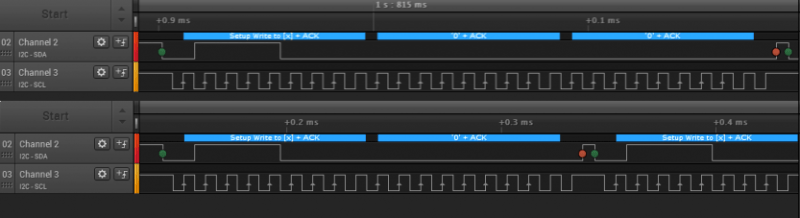
Take a look at the physical layer:
Writing a byte over I2C takes a Start Bit, Address (write bit as 0), a register address, a byte of data, and a Stop Bit.
A read requires the same Start Bit, Address (write bit as 0), the register to “write”, a Stop, a Start, the Address again (read bit as 1 because the Start bit cleared the bus), and an additional byte of clocks to read a byte. The register address to be “read” is simply a write that was never allowed to take place. It exists only to latch the Address across to a device for later consumption.
I’m not a fan of clock stretching because a device which implements it and doesn’t time out locks up the entire bus. You can’t clear the fault by sending clock pulses because the devices on the bus can’t see it (the line is held low). It’s usable in point-to-point systems, but if it’s being used as part of a shared bus then power cycling every device on the bus by GPIO to clear the stalled condition wipes away any savings of pins made vs just using interrupt pins in the first place.
SMB (https://en.wikipedia.org/wiki/System_Management_Bus) Is a newer “variant” / “extension” of the I2C protocol It also supports clock stretching, but combined with a timeout to prevent complete lockups. (And there are some more differences, but it’s “mostly compatible”
And for the 7 / 8 bit addressing. It’s a nuisance to deal with bit shifting in software. It would have been much more convenient if it was defined as an 8 bit address Or even if the R/W bit was the MSB instead of the LSB. Defining something as an 7-bit address space in microcontroller world is a big invitation for implementation incompatibilities.
I2C is also not a simple bus. There are a lot of little details and partial implementations. The stupid 7/8 bit addressing is one thing, clock stretching is another. Many buses do not implement a multi-master bus at all or are buggy (either hardware, software or both have problems).
Another big source of headaches for I2C are the passive pullups. You always have to verify with an oscilloscope whether the rise times are acceptable with your bus speed. And then you increase the clock speed in software and it does not work anymore… You also can not verify this with a logic analyzer. It’s even possible the bus looks good (enough) on a logic analyzer if it triggers on different logic levels.
That’s why I liked the old-school Philips datasheets which showed address byte with all the bits filled out:
+—+—+—+—+—-+—-+—-+—–+
| 1 | 0 | 1 | 0 | A2 | A1 | A0 | R/W |
+—+—+—+—+—-+—-+—-+—–+
No guessing needed.
Agreed, and considering that Philips is where the I2C bus comes from, I would like to say that the definition is the proper one to use.
And it isn’t difficult for the address to change between read and write (just add a one, no bit shifting or other “difficulties” required, simply use:
I2C_ADDRESS + 1;
If we change the definition of things, we only create confusion. Stating that newer datasheets do it “better” may be so, but to have two definitions for the same things isn’t better, is it? Confusion is the basis for bugs…
Anyway, the box has been opened, there is no way back, there are two definitions and we are (should be) all aware of it, so we just have to get used to it. In doubt, just try them both and see which one works and go with that. How hard can it be?
Philips is also the reason we had to say things like “Two-Wire” instead of “I2C”, so I’m not going to take them for gospel – standard writers make mistakes all the time. It’s up to us to organize things in a way that makes the most sense, and works as universally as possible – by now, many places have adopted the distinction. Addresses are 7-bit by their nature, the read-write bit is part of the protocol, and since we now have 10-bit addresses, even, it’s all that more sensible for us to drop the 8-bit part. Also, creating confusion is really a misnomer. If you see separate read and write addresses shown in the datasheet, that’s 8-bit, and if you don’t, it’s 7-bit.
philips and derivatives tend to srick with 8bit address, which is their perogative. They invented i2c. What happened thoigh, as it often does, people working with it started to treat it in a more logical and easier fashion, naturally.
So now theres two ways. And philips cant easily adopt the better way either, as either they dont follow their own spec, or had to issue an useless update to the spec.
My theory anyway …
Though I’m not convinced about some of the (very meager and examples-less) wordings of simple and register. An SPI bus is almost by definition a shift register. So a SPI based display would be as well.
Further more, I wouldnt use the term “the slave sends data”, as the master is really just reading a register from the slave. Sure the slave has to prepare stuff and make sure that the read will get the data, but its not activily sending anyrhin is it?
I am not 100% convinced by “simple” and “register”, either, I’m sure there can be better ones. However, this ain’t SPI, and “register” here does refer to a memory location, in the exact way you will see “register” written in datasheets. As for “sending data” – sounds like a distinction introducing nuance where I’d say simplicity is called for instead.
It’s worth noting that there are some higher-capacity EEPROMs that use 8-bit addressing but respond to several addresses, so bytes 0..255 are available at 0x50, bytes 256..511 are at address 0x51 etc.
It seems like that would have likely been done for compatibility reasons so that code designed for 8 bit addressing EEPROMs would work fine and just treat the larger EEPROM as two separate EEPROMs but by using two addresses like that it uses more addresses than it really needs to and it only has a size of 256 bytes. This may be fine if you don’t have much on the bus or if you stop at only two addresses but quite quickly it could become a lot more annoying than just adapting the system to use a 16 but addressing EEPROM.