There’s a special kind of satisfaction found in the act of repairing a previously broken device, which is why YouTube is full of repair channels and guides on how to do it yourself. Inspired by this, [Doug Brown] decided to give it a shot himself, with an Elgato HD60 S HDMI capture device as the patient. As per the eBay listing, the device did not show up as a USB device when connected to a computer — a quick probing of the innards revealed that not only were the board voltages being dragged down, but some of the components on the PCB were getting suspiciously hot.
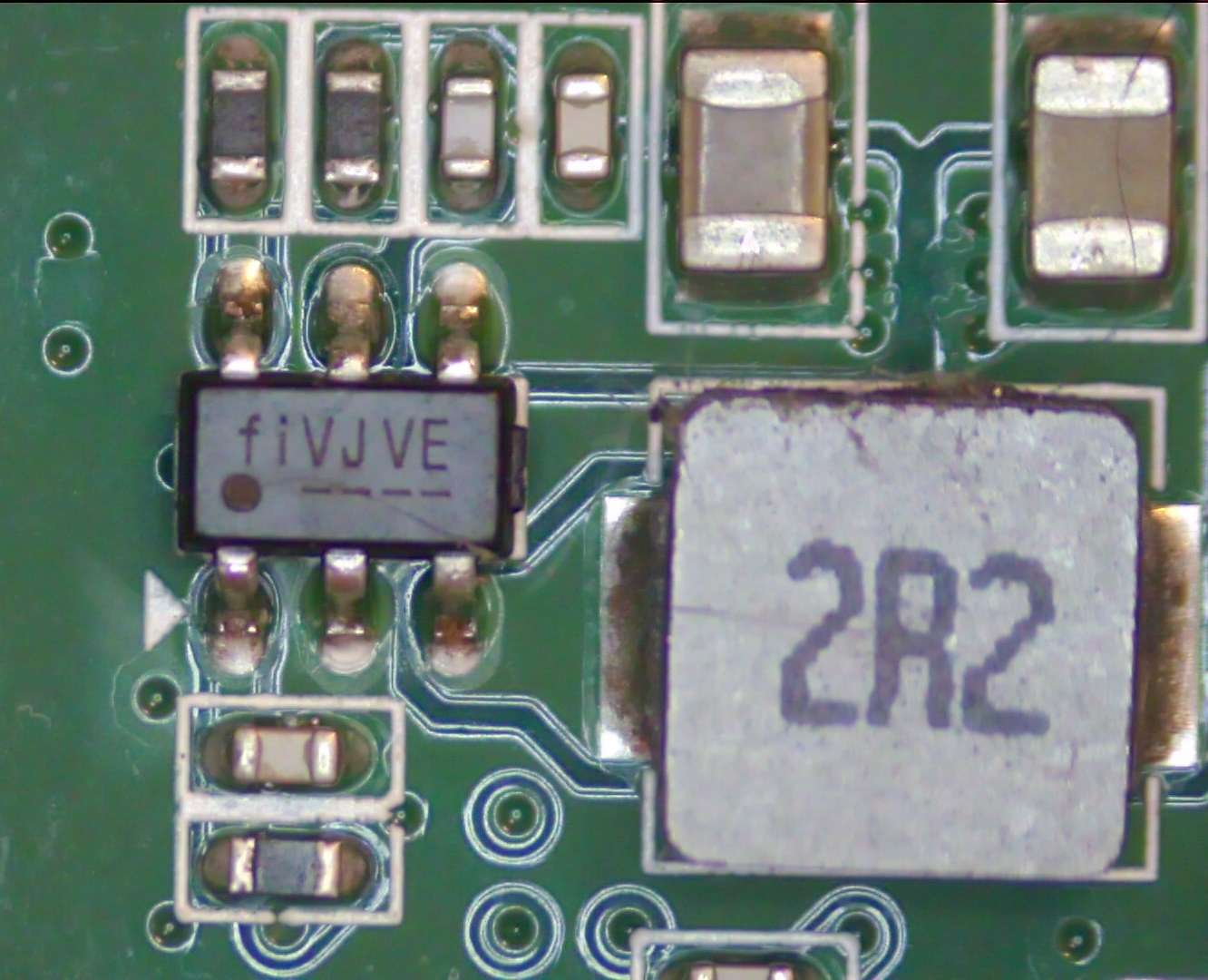
On a thermal camera the hot components in question turned out to part of the voltage regulator circuits, one a switching regulator (marked fiVJVE, for Fitipower FP6373A) and another a voltage inverter marked PFNI (Ti TPS60403DBV).
Since both took 5 V, the suspicion was an over-voltage event on the USB side. After replacing the FP6373A and TPS60403 with newly purchased ones, the voltage rails were indeed healthy, and the Elgato sprung to life and could be used for HDMI capture and pass-through. However, the device’s onboard LEDs stubbornly refused to follow the boot-up pattern or show any other color patterns. Was this just a busted Innotech IT1504 LED driver IC?
Swapping it with a pin-compatible Macroblock MB15040 didn’t improve the situation, and the LEDs worked fine when externally controlling the MB15040 on its SPI bus, as well as with the original IT1504. Asking Elgato whether there was a known issue with these status LEDs didn’t lead to anything, so [Doug] decided to tackle the presumed source of the problem: the Nuvoton M031LD2AE MCU that’s supposed to drive the LED driver IC. The PCB helpfully provides a 4-pin JST connector on the board for the MCU’s SWD interface, but Elgato did protect the flash contents, so a straight dump wasn’t going to work.
The binary firmware is however helpfully available from Elgato, with the MCU already running the latest version. This is the point where [Doug] loaded the firmware into Ghidra to begin to understand what exactly this firmware was supposed to be doing. Putting on a fresh MCU with the correct firmware definitely worked, but debugging was hard as the new MCU also enabled protections, so in Ghidra the offending code for this was identified and neutralized, finally allowing for on-chip debugging and leading down another rabbit hole only to find an SPI flash chip at the end.
Ultimately it turned out that all the hardware was working fine. The problem ended up being that the LED patterns stored on the SPI EEPROM had become corrupted, which caused the Nuvoton MCU to skip over them. The same issue was confirmed on a second HD60 S, which makes it seem that this is a common issue with these Elgato capture devices. As a next step [Doug] hopes to figure out a way to more easily fix this issue, as even the streamlined process is still quite convoluted. Whether it is an issue with Elgato’s software or firmware (updater) is unknown at this point, but at least there seems to be a fix for now, even if Elgato support seems to just tell owners to ‘ignore it if capturing works’.
There’s nothing quite as inspirational as reading about a successful repair. If you need another shot of endorphins, check out the work [BuyItFixIt] put into a video baby monitor to bring it back online.


Nice work!
This is some excellent troubleshooting at work here. Great documentation too! Nice job Doug!