For serious high-voltage plasma, you need a serious transformer. [Jay Bowles] from Plasma Channel is taking his projects to the next level, so he built a beefy 6000:1 flyback transformer.
[Jay] first built a driving circuit for his dream transformer, starting with a simple 555 circuit and three MOSFETs in parallel to handle 90 A of current. This led to an unexpected lesson on the necessity for transistor matching as one of them let out the Magic Smoke. On his second attempt, the 555 was swapped for an adjustable pulse generator module with a display, and a single 40 A MOSFET on the output.
The transformer is built around a large 98×130 mm ferrite core, with eleven turns on the primary side. All the hard work is on the secondary side, where [Jay] designed a former to accommodate three winding sections in series. With the help of the [3D Printing Nerd], he printed PLA and resin versions but settled on the resin since it likely provided better isolation.
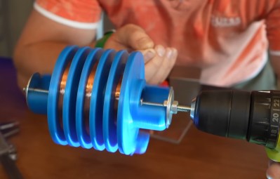
 [Jay] spent six hours of quality time with a drill, winding 4000 feet (~1200 m) of enameled wire. On the initial test of the transformer, he got inch-long arcs on just 6 V and 15 W of input power. Before pushing the transformer to its full potential, he potted the secondary side in epoxy to reduce the chances of shorts between the windings.
Unfortunately, the vacuum chamber hadn’t removed enough of the air during potting, which caused a complete short of the middle winding as the input started pushing 11 V. This turned the transformer into a beautiful copper and epoxy paperweight, forcing [Jay] to start again from scratch.
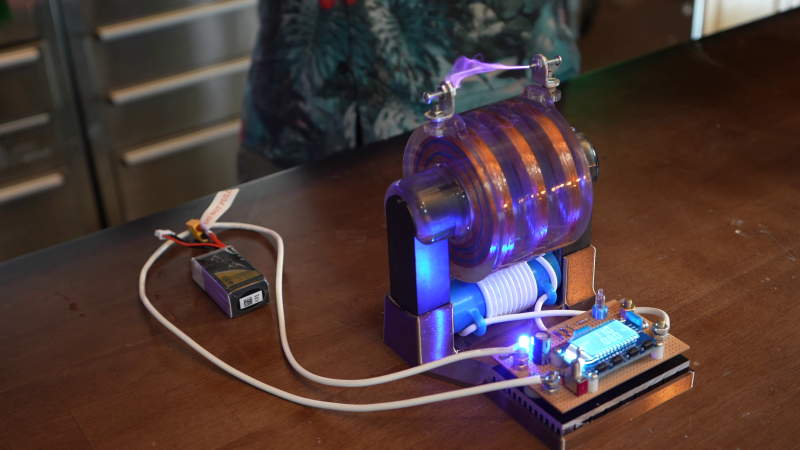
On the following attempt [Jay] took his time during the potting process, and added sharp adjustable electrodes to act as voltage limiters on the output. The result is beautiful 2.25-inch plasma arcs on only 11 V and 100 W input power. This also meant he could power it with a single 580 mAh 3S LiPo for power.
[Jay] plans to use his new transformer to test materials he intends to use in future plasma ball, ion thruster, and rail gun projects. We’ll be keeping an eye out for those!


“Shatters all voltage records”
That kind of hype is what I dislike most about YouTube!
“Commenter Formerly Known As Ren Shatters all Dislike-of-Youtube-Hype Records”
(LOL!)
Thanks 😊
You won’t believe The Commenter Formerly Known As Ren’s reaction to this hilarious comment!
Are you familiar with a voltage gain greater than his 6000x? That’s even pushing Tesla coil gain numbers.
I see in the photo 3 or so inch sparks.
You mean governments or industry haven’t done that before..
You seem to have not watched the full video. He claimed voltage gain (magnification to him). Voltage gain is different from voltage magnitude. Totally different things my friend. Not hard to do what he did, or beat it, using a Tesla coil plugged into a wall outlet. But plugging into the wall means starting with 120 volts or more. He started with 11 volts, which is only 9% of that. Unless you know an example where voltage is multiplied by more than 6000x by a single winding transformer, then his claim stands. The nerd did a good job.
I agree in principle. But I can’t resist mentioning that technically, people had very high levels of magnification over 100 years ago. After all, ignition coils / ignition magneto transformers turn several volts into tens of thousands. (I know that is only in the form of pulses as the field collapses rather than being a continuous wave transformer, but technically the voltage ratio is still very high).
There is no transformer involved in flyback tpoplogy.
Call them coupled inductors if you want, then, but hundreds of millions of television flyback transformers stand to counter your absurd claim.
The real question is whether the circuit [Jay] built is really using a flyback technique here, or a conventional transformer (implied by his 6000:1 claim) or it’s a resonant transformer (made obvious by the 10.7 kHz sweet spot he shows).
With so many secondary turns, there is bound to be substantial inter-turn capacitance. I suspect that causes resonant peaking behavior. MOSFET capacitance could also be a cause. Both will resonate with the substantial inductance. I’d love to see measured LCR parameters of the transformer to try and simulate it.
Makes me wonder if it would be possible to make new flybacks for televisions and old compact macs.
They are still available, new old stock for older TVs, new equivalents of old designs, and plenty more currently being made for things like CO2 laser supplies. But if you want to roll your own new one, that’s possible too, but I’ll tell you it’s a pain in the butt without a good coil winder.
My grandfather’s book on “Building an Induction Coil” claims 8 inch sparks from 12V input, so I think he’s missing something with his meagre 6000x amplification.
You can’t just say something like that without giving the name of the book.
https://babel.hathitrust.org/cgi/pt?id=uiuo.ark:/13960/t80k5rw8c&seq=117
“…in the English Mechanic of August 5, 1870, a method of constructing a sectionally-wound coil giving 8-inch sparks was described by “Indocturium”, in which the divisions (there being 90 sections) consisted of separate ebonite discs slipped on one by one over the ebonite tube with distance pieces or rings between.”
They are describing the construction of an induction coil with the secondary constructed in short sections to limit the amount of voltage at each section, avoiding arcing and leakage through capacitance over the insulation. These are then connected in series externally.
These are devices that are constructed like transformers, but operate on the self-induction principle where you rapidly introduce or cut off the primary current and the transient resonant oscillation of the coils causes the voltage to rise about 10x over the turns ratio of the transformer.
They also describe the “Scottiswoode Coil” producing 34″ sparks out of a 19 Volt battery. With more batteries, they got 42″ sparks. These were enormous devices weighing in at over 100 lbs and required two men to lift for swapping out the coils.
With self-inductance taken into account, the simple “amplification” factor of the coil is only about 1:2000 to 1:3000 though. They added Leyden jars (capacitors) to the secondary and then dialed in the switching frequency of the mechanical interrupter (basically a relay buzzer) to make it operate much like a Tesla coil. Then they observed the sparks using a rotating mirror to act as a kind of a synchronized shutter to see the spark as it progresses through the switching cycle.
The mechanical switch operates fairly slowly at something like 80 Hz, but the added capacitance slows down the oscillation enough that it doesn’t die down between current pulses and the energy keeps adding up in resonance, pumping the voltage higher and higher.
Induction (Rühmkorff) coils can create generate high-voltage pulses of up to around 250 kV. One of the world’s largest spark inductors was built by Alfred Apps in 1877. With a wire length of over 350 km, peak voltages of around 1 MV could be achieved.
Book: The Alternate Current Transformer in Theory and Practice: https://books.google.de/books?id=j4nVAAAAMAAJ&pg=PA55&redir_esc=y#v=onepage&q&f=false