If you want to deliver the maximum power to a load — say from a transmitter to an antenna — then both the source and the load need to have the same impedance. In much of the radio communication world, that impedance happens to be 50Ω. But in the real world, your antenna may not give you quite the match you hoped for. For that reason, many hams use antenna tuners. This is especially important for modern radios that tend to fold their power output back if the mismatch is too great to protect their circuitry from high voltage spikes. But a tuner has to be adjusted, and often, you have to put a signal out over the air to make the adjustments to match your antenna to your transmitter.
There are several common designs of antenna tuners, but they all rely on some set of adjustable capacitors and inductors. The operator keys the transmitter and adjusts the knobs looking for a dip in the SWR reading. Once you know the settings for a particular frequency, you can probably just dial it back in later, but if you change frequency by too much or your antenna changes, you may have to retune.
It is polite to turn down the power as much as possible, but to make the measurements, you have to send some signal out the antenna. Or do you?
Several methods have been used in the past to adjust antennas, ranging from grid dip meters to antenna analyzers. Of course, these instruments also send a signal to the antenna, but usually, they are tiny signals, unlike the main transmitter, which may have trouble going below a watt or even five watts.
New Gear
However, a recent piece of gear can make this task almost trivial: the vector network analyzer (VNA). Ok, so the VNA isn’t really that new, but until recently, they were quite expensive and unusual. Now, you can pick one up for nearly nothing in the form of the NanoVNA.
The VNA is, of course, a little transmitter that typically has a wide range coupled with a power detector. The transmitter can sweep a band, and the device can determine how much power goes forward and backward into the device under test. That allows it to calculate the SWR easily, among other parameters.
In Practice
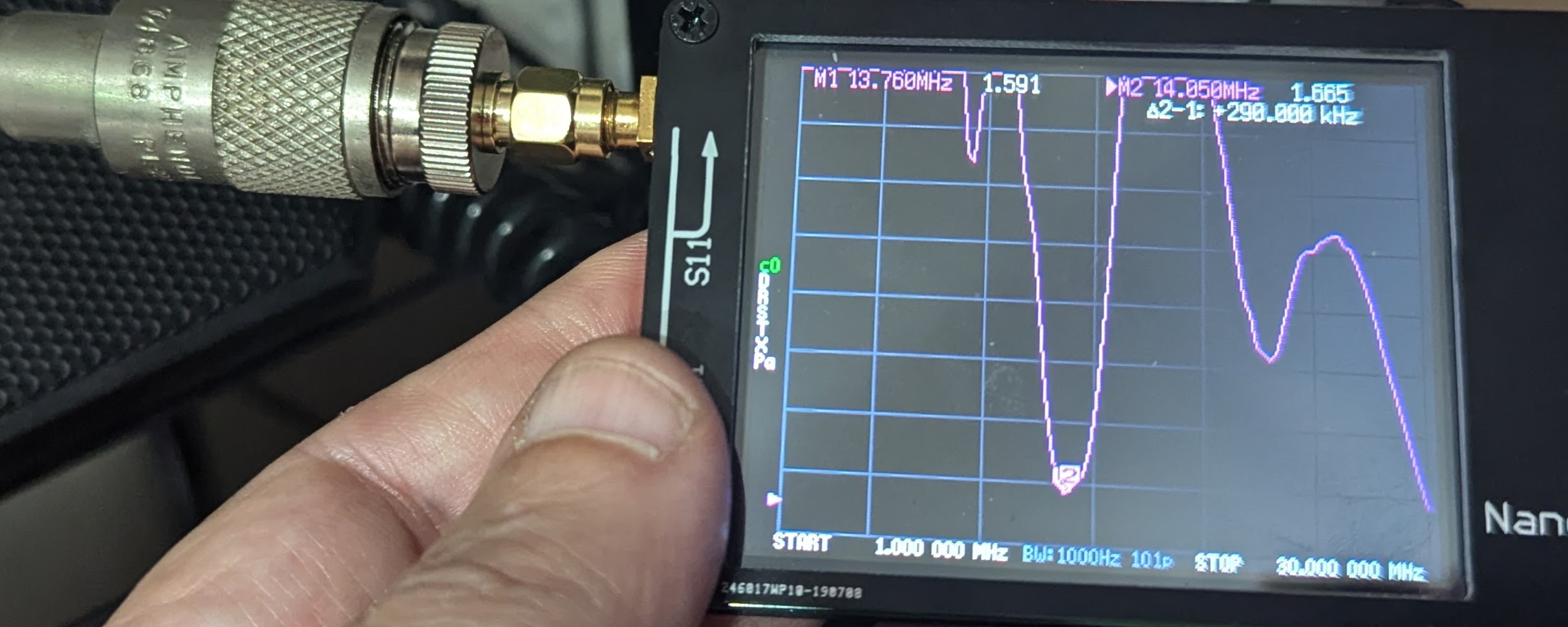
This sounds good, but how does it work? Well, to find out, I took a long wire connected to an MFJ Versa Tuner II and fed the NanoVNA’s TX port to the tuner. With the tuner in bypass, the screen looked like the first image. It actually had a pretty low SWR near 14 MHz, but everywhere else was not going to work very well at all.
The next step was to switch the tuner into the circuit. Ideally, you could infinitely vary the inductor and both capacitors, but making roller inductors is a cost, so many tuners — including this one — have switches that select taps on the inductor, meaning you can only change it in fixed steps. That isn’t usually a problem, though, because you can adjust the capacitors to make up for it.
Since you aren’t transmitting, there’s no rush, and you can easily switch things around and turn knobs until you can find a null. If you were using the actual transmitter, you’d want to avoid switching the inductor “hot” because the switch contacts won’t appreciate any high-power RF.
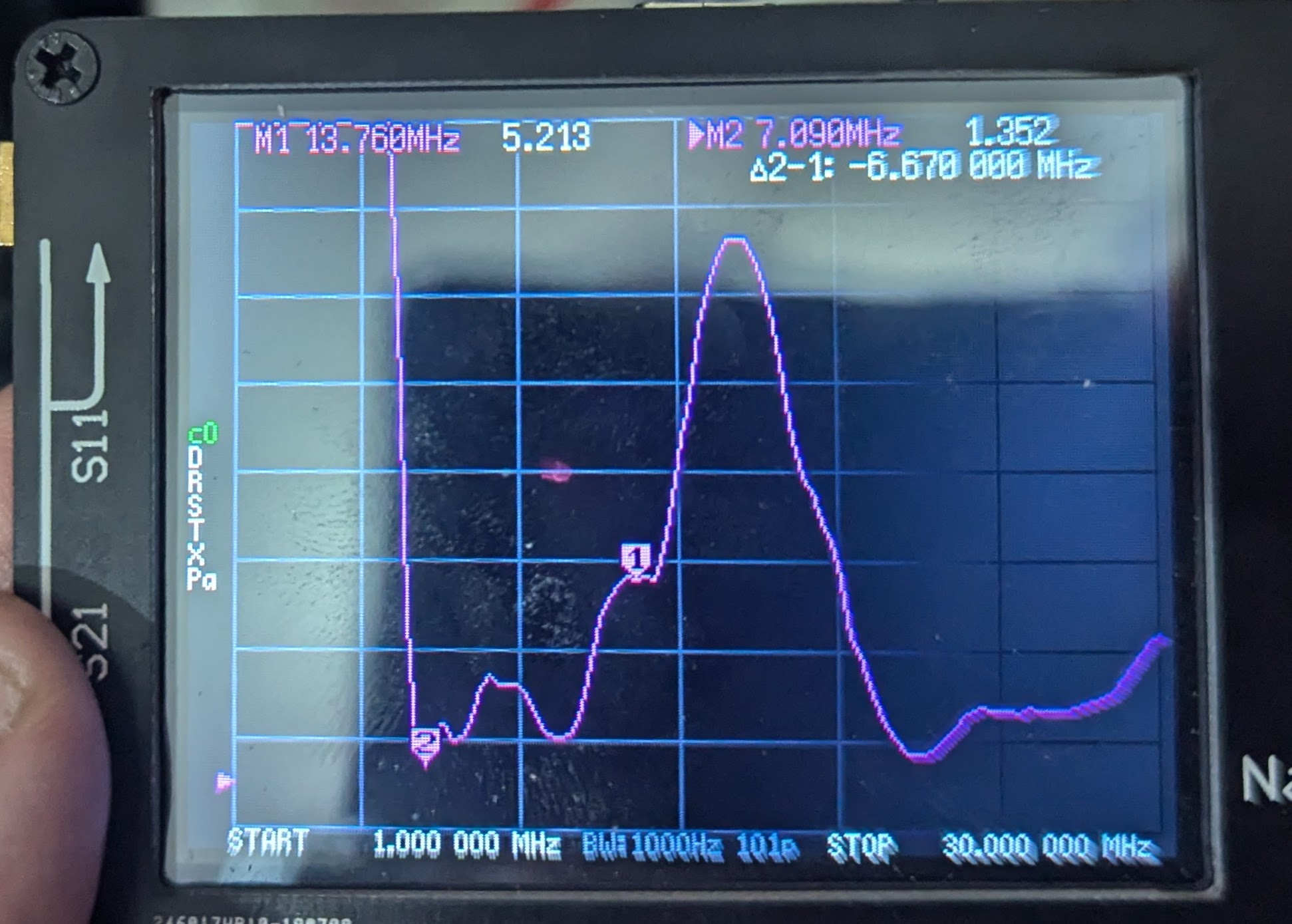
I centered the frequency range around 7 MHz and found the lowest setting I could on the tuner. Then, I zoomed back out to the entire HF band. Not bad.
I went through and found null spots for all the ham bands. It was also possible to measure the SWR for bands I can’t transmit on (for example, 15 MHz, to listen to WWV).
Once I had jotted down all the settings, it was time to reconnect the transmitter. Well, technically, a transceiver — in this case, an Icom IC-7300. Even without transmitting, having the knobs adjusted correctly definitely helped with receiving, often strikingly so.
But Did It Really Work?
My first attempt was to use the frequency exactly where I had tuned before switching in the transmitter. As you’d expect, the transmitter saw a low SWR and had no issues, but changing frequencies was a little different.
The knobs on the tuner are not especially precise. Some high-end devices have multi-turn knobs with counters to help you get exactly back to some setting, but this tuner has no such thing. So when the dot on the knob is on, say, “2,” it is hard to know for sure if it is exactly where you had it last time it was in the same position.
However, you can get close. Changing frequencies and tuner settings would sometimes give me a great SWR, but sometimes it was a little high (never any more than, maybe, 1.5:1). A minor tweak of the two capacitors on the tuner would resolve it quite easily.
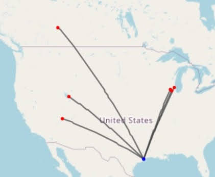
A quick CQ on 15 meters resulted in the map you can see from the reverse beacon network. The furthest away I was heard was a bit more than 1,800 miles away. Not bad for a fairly short wire hung over a tree. Subsequent testing on several bands resulted in many contacts across four continents in a few hours.
Takeaway
Do you need to use a VNA to tune? No, but it sure is handy. Sure, it generates a tiny signal, but nothing like your transmitter. I like tuning very quietly and precisely without risking the expensive final amplifiers in my station. A good tuner can load up almost anything, and while you won’t get the performance you would get out of a proper antenna, you can still get on the air and have a lot of fun.
Of course, the VNA can do other things too. It can characterize components and modules like filters. You can even use them as time domain reflectometers to troubleshoot cables. It is worth noting that while I took pictures of the VNA so you could see what it would look like, it is actually better to use one of several programs on your PC that can create graphs and data that would be easy to work with. For example, I often use this one.
Want more things to do with your VNA? You can even map antenna patterns with one.


Even with a VNA it’s not silent, you can hear the signal being injected with your radio nearby.
I routinely do this when tuning my magnetic loop antenna because it’s extremely narrowband.
Yeah, well:
It is still better than pumping out even 5W over your antenna. Plus you can turn tap switches without worrying about arcing, etc.
Yep. Though low power, the characteristic sweep of the VNA is clearly audible on the air.
If you want to be totally silent, use a noise bridge approach. I can’t do it justice, so here’s a description: https://palomar-engineers.com/wp-content/uploads/Antenna-Tuning-with-a-Noise-Bridge.pdf
A noise bridge isn’t silent either … it just uses noise as signal source instead of a single signal.
Yeah, it can be a little difficult to understand how a noise bridge works from an RF standpoint, but basically, you’re taking a noise source, splitting it, and doing a differential measurement across the half of the signal on the way to a 50 ohm termination and the half of the signal on the way to the antenna.
If the two devices have the same load impedance (the antenna is properly matched at the target frequency) the difference will be zero – but that means that the antenna is transmitting all of the noise that’s being fed to it.
Again it’s not a lot of signal compared to when you actually transmit, but it definitely ain’t silent.
Yep, duh, brain fart. Was thinking of another tuning technique using (thermal) noise. Thanks for the fix.
My radio has a rad waterfall
Display and I always see sweeps a’comin my way. Always wondered what those were and yes. They are super annoying. Anything to minimize that is well appreciated.
That’s ionosonde doing their job
Ah yes, the noise bridge. Older hams had recommended using it, when I planned to build a shortwave antenna.
The noise bridge is a very old tool, like the grid-dip meter. Not bad, but somewhat oldschool and equally hard to get now.
You can make one with a 555
https://randysbench.wordpress.com/2015/01/02/antenna-noise-bridge/
Another vendor will eventually take over manufacturing auto-tuners like the MFJ-988, now that MFJ is gone. I think the owner of MFJ was too old to go on and wasn’t offered as much for the business as the real estate was worth, and thus he shut it down along with the half-dozen ham radio companies he had bought. Not a really nice goodbye for us hams.
The 988 was located at the antenna rather than in the shack, because it’s more effective that way than attempting to tune the antenna through a long coaxial cable which has a fixed impedance. It used phantom power over the coaxial cable. It would be better if a new unit took data from the transceiver, since most these days can indicate their VFO frequency over a data line, and tuned via its own RF emitter rather than the transmitter, and only then gated the transmitter on. This would take an additional wire for communications.
I can never find it, but Heathkit (I think) had an antenna many years ago that was good for people with big yards. The idea was you put up a very long wire dipole longer than the lowest frequency you wanted to use. Because it was “too long” it was an inductive load. So there was an air variable capacitor at the feedpoint tied to a selsyn/synchro whatever you want to call it. The other end of the synchro was in the shack (with wires, of course). So you turned the capacitor to null out the inductive part of the load. The old tube transmitters could easily load up anything resistive. I can never find that in the old catalogs so I don’t know if I am misremebering it or what. Maybe it was just a motor with up/down buttons in the shack, too. It has been a long, long time ago so hard to remember.
One was made by a cottage manufacturer, and I picked it up at a ham swap meet. It wants the dipole to be about 10% long and has a variable capacitor driven by a motor that goes in the center.
And of course the SteppIR are a variable length vertical in a fixed length radome.
There’s a manufacturer at Hamvention who sells a box that implements a physically variable length dipole. It uses wire and rope. I think there’s a German company that makes a remote balanced tuner. In the kind that I first saw from SGC for sailboat use, and was later cloned by MFJ switches both resistors and capacitors in, I think, a pi matching network.
Antenna tuners from LDG Electronics are a great option. The company is led by founder Dwayne Kincaid (WD8OYG).
MFJ is gone?! Nooooooooo! They always had what I needed at the right price.
There was an article about this in various amateur radio magazines.
If I remember correctly, the owner of MFJ had spent many years to the amateurs and now wanted to spend his remaining time with family.
The pandemic was also a reason here, maybe. MFJ didn’t fully recover from it, either.
“They always had what I needed at the right price.”
I don’t know. Comparing an classic 1970s MFJ antenna tuner (such as MFJ 16010) to same model from 21th century was, um, interesting.
That is a great idea, the best I have heard in years. Its so obvious and no one has done it yet. Perhaps someone will instead come up with an add-on box that takes control of the transceiver to do tbe job. If I were 50 years younger I certainly would design one. Chris. KC1KWX
There is literally zero functional difference between using an antenna analyzer (like the ones that have been around for decades) and a VNA in S11 mode for use with an antenna tuner to tune an antenna. The ONLY difference is that the more recent low end VNAs are cheaper. I did this same thing with an AEA HF-CIA about 25 years ago and others were doing it long before me.
Can anyone say, smith chart? I’m never going to painstakingly record hundreds of single-point readings from an antenna especially when it’s going to vary as things sway in the wind or as I hold them. A SWR meter is a single point with no complex reading. A random antenna analyzer may give you a SWR curve plotted across a frequency range but only give you a single-point complex impedance reading. But these vna’s plot that as well, such that you can properly compute what you want by standard smith chart operations or infer the situation from the shapes you’re seeing. So instead of “Hey my antenna is xyz amount capacitive here” or “let me twiddle the knobs in sequence until i get a good reading” you can look at it differently. Maybe you have an antenna that for whatever reason comes up as about 10-100j on your primary band of interest. With the right amount of transmission line, you can rotate around the chart so that tuning it requires quite reasonable values of series and parallel capacitance, which can be provided by some cheap air variable caps. With the wrong length, you might need a big tapped inductor that loses more power than the extra transmission line length ever would. Mind you, I rather things be more convenient than that, but still.
Absolutely none of that is true. I didn’t say SWR meter … I said antenna analyzer. Antenna analyzers have for decades been able to display R +/- jX and with that you can trivially see which direction you need to tune the elements of the tuner … exactly like you would with a Smith chart display. My old HF-CIA (I originally paid around $200 for it) is over 30 years old and displays R +/- jX as a curve on an LCD display over whichever bandwidth I tell it to. Look it up if you don’t believe me … they can still be purchased used. Similar consumer units from other manufacturers showed up not long afterward.
I’m amazed how you instantly decide I must be an idiot. Let me try again.
I believe that nowadays basically any VNA worth having is going to be usable for everything we’ve been discussing. I also believe that just because your antenna analyzer might have had nice features doesn’t mean that a “random”, typical, common, average, normal example of an antenna analyzer was always like that. I think a normal example would be closer to a mfj-259d.
I also think most people’s plots were typically a rectangle where the x-axis represented frequency and the y-axis represented another real number. So since a complex number needs two real numbers to express, but you only have one axis left, you would need two different plots – one for the real portion and one for the imaginary portion. You can overlay them if that’s supported, but it may well not be. I used one not even ten years ago (though it may have been a few years old at that point). It could only plot one variable at a time, so if you wanted complex numbers you needed to read them off as single points because you couldn’t get both real and imaginary portions onscreen at once any other way. And if they’re not onscreen at the same time, then like I mentioned with the wind, they can have varied by the time you take the other reading. At least the single-point measurement has both parts taken simultaneously. Data-logging to a computer could solve it, but we’re talking portable use here.
There’s a real UI advantage in plotting differently. And there’s a real difference in the liklihood of any random device supporting various features if it’s calling itself a VNA versus an antenna analyzer.
I didn’t say you were an idiot, but you are pretty sadly uniformed. You made the assumptions, not me. And by the way, there is zero difference between an antenna analyzer and a VNA used in S11 mode. Antenna analyzers (I have three different ones spanning 30 years) can can plot real, imaginary, or both. VNA’s ( I have two of them) can plot real, imaginary, or both. If you think there is an actual functional difference, I’d like to hear it.
Can I just say that the NanoVNA is an awesome piece of gear at an incredibly low price? It’s not an HP or anything, but it’s a heck of a piece of gear well within a home hacker’s budget, and that’s great. It fills a huge gap.
Yeah, it’s a neat toy. And I mean it, a toy. Still useful, though.
A commercial network analyzer may provide more trustworthy results.
Like when measuring reflections on coaxial cables (other end must be terminated by a dummy load).
Something like an Rig Expert analyzer does make much less errors here.
By contrast, relying purely on a nanoVNA makes you hunt phantoms eventually.
Also important is to learn to how to handle a VNA properly.
Ideally, antennas should be measured in the wide open, away from obstacles that can distort their radiation pattern.
I see HP network analyzers for sale cheap compared to scopes. I thought they were for computer networks. Are there two different types?
Yes, the one you want is a Vector Network Analyzer, but buying one of the old ones without knowing what you’re doing is going to be a problem. Even the right cables for them can cost hundreds of dollars, even the genderless connectors with repeatable SWR per connection cost hundreds. Good luck if you buy a unit without them.
You can find T1 Network analyzers which look awesome and are completely useless and sell for a couple dollars.
If you’re selling them, yes, it’s important to measure antennas in the wide open. If you’re USING them, on the other hand, especially for non-hobby things where success is a requirement, you should be measuring them in situ, where their pattern and impedance are distorted by the same factors that will affect their actual use.
Mostly not a ham topic, I know, but…
One of the advantages of the older style manual turner is it’s actually quite easy to get very close to tune just by listening to the background static’s volume and picking the peak.
That lets you get your on air tune up time way down, often just enough to verify your vswr is well under 1.5 without a need for further adjustment.
I like my auto tuner a lot, but i think the manual tuners are better.
With some of the modern tools available to us i think it’s possivle to replicate that manual process on an auto tuner, but i haven’t got around to trying it yet.
Another advantage of lexx expensive, manual tuners is that they can be left outside in a little waterproof box, close to the antenna.
Using an auto tuner in the shack is so CB radio level, skill wise.
The transformation proccess should never be extended to the coaxial cable, but merely happen at the antenna feed point.
What are you talking about? A manual tuner at the antenna?? I’m picturing you running outside in the rain to change frequency.
Besides, a tuner in the shack is absolutely fine if the length of coax isn’t too long and if it has low loss. The difference in the on-the-air signal is virtually imperceptible.
“What are you talking about? A manual tuner at the antenna?”
Sure. Something simple like an MFJ 16010, for example.
It’s a pi filter, essentially. You can also build yorself one. It belongs close to the feedpoint.
Using a little coaxial cable for connection is okay, though.
If your radio is in the house next to a window and you’re a having a long wire antenna going down the garden, then the tiner can be placed in the house, were the feedpoint of the antenna is.
It wasn’t too uncommon to have a banana plug with the wire being inserted into the outgoing UHF connector of the matchbox.
“Besides, a tuner in the shack is absolutely fine if the length of coax isn’t too long and if it has low loss. The difference in the on-the-air signal is virtually imperceptible.”
No, I don’t think so. That’s not the point, also.
The point is, that the feeding cable, the coaxial cable, shouldn’t be “tuned”.
Otherwise, it radiates in worst case, have sheath current etc.
Or the radiation pattern of the antenna will simply be mixed up.
A tuner, a matchbox, does belong to the antenna.
To essentially perform the role of a matching coil that some antenna types have built-in. Physics can’t be haggled over.
The shiny automatic antenna tuners are best to be used on a field day. Same goes for the combo matchbox/vswr meters that CB operators use.
It’s better to use enclosed, waterproof auto tuners that can be remote controlled from shack.
Auto tuners that have no displays and can be mounted outdoors with bolts and screws on a pole or the housewall.
LOTS of incorrect comments there.
All of a sudden you’re talking about an end fed antenna with the feed right outside your window. That’s hardly a general case. Anything further away is ridiculous for a manual tuner. You’re just talking about a fixed network that you don’t have to change … not the same thing.
“It wasn’t too uncommon to have a banana plug with the wire being inserted into the outgoing UHF connector of the matchbox.” … which was and still is an excellent way to guarantee you had RF in the shack.
A high SWR on the coax DOES NOT inherently mean that the coax radiates or messes up the pattern f the antenna. I don’t know where you got that idea, but you certainly don’t understand how coax works if you believe that. Balanced antennas without common mode chokes (or some other transformation from balanced to unbalanced) on the unbalanced coax cable result in currents on the outside of the sheath, not SWR … they are two different things.
Of course a tuner at the antenna is ideal … assuming it has low enough loss since a low loss tuner in the shack might be better than a lossy one at the antenna depending upon the loss of the coax. But a good tuner in the shack with low loss coax could easily have low enough total loss that nobody could tell the difference in signal strength in spite of what you “think”. The additional loss due to a 5:1 SWR on 100 feet of relatively common LMR400 coax at 14 MHz is only 0.65 dB. I guarantee that you cannot discern that as a difference by ear. You easily can (but probably won’t) verify that by using the application TLW that comes with the ARRL Antenna Book.
@AZdave I’m afraid you either don’t understand me or you don’t want to understand me. Maybe it’s my English, also, not sure.
What I said about the end fed antenna was nothing unusual. It was a legit example.
It was about how to use a matchbox/antenna tuner, if it’s being properly used in the house.
A long wire antenna that goes from your shack’s window down into the garden was the classic way of setting up a quick antenna.
That was the only situation in which the antenna tuner had a rightful place in the house: near the window, were the ham transceiver was located; close to the end of the antenna, which comes into the room from the window.
@AZdave I beg your pardon, but I didn’t mean to talk about SWR here but about the unwanted effects on careless tuner use.
I also think that a coaxial cable can radiate under certain circumstances. Like a radial of an antenna can do.
To be fair, sheath currents alone are bad enough already, though.
Using an 1:1 balun (current balun) is recommended, thus. At the antenna feedpoint, of course. ;)
vy73s
No … an end fed antenna is NOT the only situation where a tuner is appropriate in the shack. Did you not read or understand my example of a 5:1 SWR on 100 feet of LMR coax???? The additional loss due to the SWR on the line is negligible.
“What are you talking about? A manual tuner at the antenna?? I’m picturing you running outside in the rain to change frequency.”
Yes and no. You take your transceiver outdoor once to adjust the antenna for your favorite frequency.
Such as the CW area of 20m band, for example. Or the telephony area of your local 80m round.
This assumes that you are going set up a mono band antenna, of course.
The only proper antenna in my opinion. If you have multiple mono band antennas, you have multiple tuners in use.
A multi-band antenna like W3DZZ shouldn’t require an external tuner.
You as the operator do configure the antenna during installation according to your needs.
By varying the length and use of traps you can modify the antenna as you like.
“What are you talking about? A manual tuner at the antenna?? I’m picturing you running outside in the rain to change frequency.”
Since this is HaD: t’s also possible to add a motor (with gears) to the variable capacitor and “fine tune” it from the the distance.
Or use an relect-mechanical relays and a fixed capacity (a condenser).
By activating the relays from the distance, the capacitor will be wired in parallel to the variable capacitor.
That way, it’s possible to have another frequency being tuned to.
By adding multiple relays, this idea can be extended.
The relays can also be used to physically extend an antenna,
or to short a part of it.
There are many possibilities. It’s all better than using an antenna tuner in the shack.
Vy73s
I’m with you. The early automatic antenna tuners used DC Motors to turn air variables. However, there was no memory or feedback like in a stepper motor. A new tune would be required each time the transmit frequency was changed. Perhaps starting with one of these and adding stepper motors or encoders would make half of the project pre-built. Chris.
I have a NanoVNA, it’s fantastic for antenna building.
But vSWR is really only half the story. It’s useful if you’ve got a range of frequencies you are using an antenna for but not so good when you’ve got a fixed frequency or very narrow band.
For a given frequency, when you’ve got a mismatched antenna, it’s useful to know what direction the mismatch is.
Enter the Smith Chart. The NanoVNA can plot the load on a Smith chart which tells you exactly how much parallel or series capacitance or inductance you need to add to get a match. That’s the real power behind it.
It’s worth noting that the “V” aspect of the VNA is going unused here, it’s essentially acting as a scalar network analyzer, similar to an antenna analyzer. Nothing at all wrong with that. But if you want to be a bit more scientific about things you could take a vector measurement and use that to determine a good starting point for the tuning inductance and capacitance. And if you really wanted to dial things in, you’d put the tuning network at the antenna feedpoint and apply port extensions to the VNA to measure the impedance at that point. But it might get old hauling out the ladder every time you change bands.
There’s a reasonably good treatment of antenna tuning here: https://www.antenna-theory.com/tutorial/smith/smithchart5.php
After a few dozen tuning exercises, which tuning topology to use and the way series and shunt elements shift things on the Smith chart becomes muscle memory, as does the approximate effect of certain values at certain frequencies. Tuning with discrete components is often a highly iterative process, particularly at 2.4 GHz and above, due to circuit and component parasitic effects. A millimeter of transmission line between components means it’s no longer really a lumped element match and more of a complex network. In the MHz and tens of MHz under consideration here, it’s much more straightforward.
So long as one stays “on the side of the road” when tuning – not in the middle of a standing QSO, identifying and limiting transmissions to five to ten seconds at a few watts, they’ll be OK. If the antenna is so far off that it requires heavy tuning, the ERP is going to suffer no matter what, limiting propagation, and there’s little risk of damaging equipment at such a low power. And if it’s so far off, a matching transformer or balun may be called for anyway.
Doesn’t the 7300 have an internal antenna tuner? Can someone less daft than me explain why you’d use an external tuner you have to dink with every time you change bands instead of just push the “auto tune” or whatever iCom calls it and be done?
Measuring the properties of your antenna is great though and agree a nanoVNA is a game changer to actually see what is going on.
The internal tuner has rather narrow range it will tune. I think Icom specifies that it will tune at most 3:1 VSWR, which is a common range for internal tuners.
So it can correct the 1.7:1 VSWR of your dipole at the band edge, but wont tune up your rain gutter on 160 meters.
And to make things work with the convenient “tune” button, many autotuners can be connected directly to the Icom with a cable.
The NanoVNA also exists as V2, now, I think. Clones may exist, too.
I vaguely remember that one version had used harmonics to extend measuring range, so be careful.
Another topic is hand capacity, maybe.
Holding the NanoVNA while measuring may give a different result than just laying it down while measuring.
Semi professional VNAs like the old Rig Expert AA-170 may not have this issue.
They’re built into a big plastic shell which provides better insultation.
FWIW, I’ve now tested half a dozen or more NanoVNAa for myself and friends against my R&S gear, in terms of frequency and measurement accuracy they stack up well, really well, far better than anyone would expect and are definitely not a toy.
I’ve never seen the ‘hand capacity’ problem you speculate about unless it was when measuring an antenna for a handheld radio but I would expect to see such effects, even with my R&S gear, if I were waving my hands around or touching the cabling, antenna mount etc..
They’re a useful, valid piece of test gear offering incredible value for money at a price point where frying one by accident won’t make you cry and they’re repairable unlike so many older commercial analysers where parts ore obsolete, unobtainable or cost as much as getting a new second hand unit.
Like all test gear, you have to know how to use it and set up your test environment correctly or you get rubbish results, when you can do that you get good data.
“I’ve never seen the ‘hand capacity’ problem you speculate about [..]”
My bad. I often make the mistake to directly translate from my own language.
I’ve should have worded it differently in English language.
The “problem” is that the nanoVNA has no real chassis, but just two plates of PCB.
When you hold the nanoVNA, you provide sort of a ground connection or a counter poise. Similar to when you’re holding a walkie-talkie.
This may result in a different measuring result, unless the antenna is being grounded already. Hope my working is better this time.
In other words, if you’re going to measuring a ground plane antenna, it’s better not to touch the nanoVNA while measuring.
It could have an effect on the function of the counterpoise, of the radials.
The radiation pattern and the impedance, too, maybe.
Commercial analyzers don’t have a metal chassis to my understanding.
Except maybe those VSWR meters made by MFJ, not sure.
But that’s amateur radio level of technology, not professional level of technology.
Their use cases are different, after all. Professionals and amateurs have different takes on certain things, I would say.
Or let’s imagine if a digital multimeter was being made with a metal chassis instead of a plastic chassis.
That would be highly unprofessional, as well, considering the lack of any insulation.
Stationary devices or portable devices are another topic.
Even older analog handheld volt meters/ohm meters who had a metal chassis did come with a leather case.
So really, the idea of choosing PCBs for nanoVNA was a bit shortsighted, I think.
It was clever from a manufacturing and economical point of view (cheeeeap!), but not from a craftmanship point of view or an electrician’s point of view.
Most Nano VNAs come with a full polymer case. They can also correct their results to account for transmission line effects between them and the antenna. Came in handy when I was given a 5 band vertical which I connect to via 50 feet (~15 meters) of coax. The VNA let me determine its electrical length by disconnecting the antenna and looking for a maximum non-reactive impedance (hooray for Smith charts!). Results of the antenna sweep showed a fault in the 80m resonance, soon found to be due to an open 80m loading coil open circuit.
Having worked 10 years at Keysight Tech headquarters (Then, Hewlett Packard Signal Analysis Division in Santa Rosa, CA) writing firmware for high end spectrum analyzers, in the same site that makes their network analyzers, I am delighted with the NanoVNA. That it can do what over a man decade of painfully created assembly coded firmware on a business envelope sized circuit board with a M68000 and 392k of EPROM is just delightful!
“Most Nano VNAs come with a full polymer case.”
Just checked, that seems to be true these days.
Back in 2010s when I got my nanoVNA it was just the bare unit.
Thank you for your Information.
“That it can do what over a man decade of painfully created assembly coded firmware on a business envelope sized circuit board with a M68000 and 392k of EPROM is just delightful!”
I see, I see were you’re coming from.
To older folks, small gadgets must be a miracle, generally speaking.
They’re fascinated by smartphones, too, because such things didn’t exist in their youth.
However, to people like me who grew up with Gameboys or Casio LCDs pocket TVs in the 90s it’s not that special.
I mean, people like me value these things, too, but are not overly excited about miniaturization.
People like me rather think it’s “normal”. Just like people of the 1970s found transistor pocket radios to be “normal”, too.
Just like such people don’t look down on C64 or NES console, generally speaking.
If it’s doing fine, then it’s okay. There’s no reason for them to make fun of the older technology or think “oh man, yeah, how far we did come!”
In fact, many younger people have no issues watching an VHS, if they’re given access to tapes and hardware. They learn fast, once shown how it works.
In other words, they don’t need to surround themselves with latest tech to feel young.
Rather contrary, they think old technology is kind of strange and cool sometimes. They’re curious about it, at least.
Personally, if the nanoVNA was the size of a 1970s cassette recorder, I would not complain, either.
It’s not “mobile” anymore by today’s standard, but still portable like a suiet case or a traveling typewriter.
And anything portable is good enough for servicing an antenna on the go.
If it’s not much bigger than a toolbox, it’s fine. It’s not necessary that if it fits in the pocket of a t-shirt.
Vy73s
“In fact, many younger people have no issues watching an VHS, if they’re given access to tapes and hardware. They learn fast, once shown how it works.”
My 20 something daughter would disagree…
The picture is too blurry for her.
That’s not the point and you know that, I assume. Most of us don’t like VHS, quality wise. ;)
I was thinking about kids between ~4 and ~16, also. Young people who still can be fascinated about something.
Those that are curious about the tech their older siblings have used, for example.
Things like CRT TVs, VHS tapes, vinyl records, music CDs, music cassettes and older consoles are “retro” these days and interesting to those.
That doesn’t mean however, that these things do be direct competition to modern tech whatsoever.
There’s no black and white thinking.
Such young people can watch films via streaming platforms casually, while also playing with a VHS player or VCR in their bedroom from time to time.
Maybe to impress their fellow young friends who haven’t being grown up with the technology anymore.
Because to us who have lived through these times, it’s nothing special anymore while to them it’s something “new”.
That was my point, also. To my generation or similar minded people like me, a nanoVNA is just “normal” while an older generation may find it highly fascinating.
I’m speaking from real life experience here, by the way.
Almost all hams I know of personally are addicted to anything “small and black”.
They throw away good old rigs with high built quality in favor of cheap consumerism tech.
They also don’t value their homebrewed equipment from 40 years ago.
I often admired their early works and saw all the hard work that went into it.
While simultanously, they didn’t. They essentially denied their younger self.
I always find this sad, because it also sends a bad message to other young amateurs who essentially are like that younger self.
Whenever old hams make fun of their younger self, they’re hurting the young hams out there who just have started.
Vy73s
“That’s not the point and you know that, I assume.”
Writing respectively, I did not see that as your point.
Speaking of VHS, the new Alien movie is being released on VHS soon.
Because VHS still is cool, I suppose. Like Windows 98SE is.
https://www.theverge.com/2024/10/20/24274915/alien-romulus-vhs-limited-edition-collectible-release-date
I hope it’s okay to provide a link to this news as a proof, I don’t mean to advertise the film whatsoever.
I liked this article. I’m a ham and generally carry some compact VNA when operating portable so I relate to the content and appreciate the advice.
A couple of other related links that might be of interest, which take the concept of silent tuning somewhat further in a couple of other contexts:
Fully automated silent tuning: https://athena.westpoint.edu/items/9acd01cb-3e48-467c-ba5d-72afd8df90fa (Melville & Hamilton)
Using an algorithm to go straight to the correct tuner settings, no need to squint at graphs in the field: https://github.com/conniest/InstantTuning (Stillinger & Melville)