At this point, many of us have gone all-in on USB-C. It’s gotten to the point that when you occasionally run across a gadget that doesn’t support being powered USB-C, the whole experience seems somewhat ridiculous. If 90% of your devices using the same power supply, that last 10% starts feeling very antiquated.
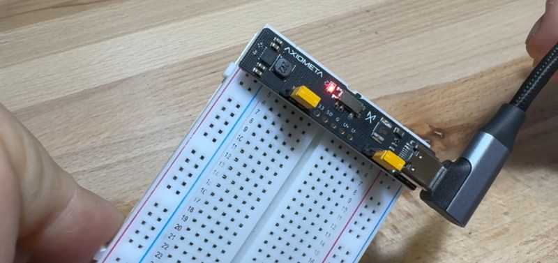
So why should your breadboard be any different? [Axiometa] has recently unveiled a simple PCB that will plug into a standard solderless breadboard to provide 3.3 and 5 VDC when connected to a USB-C power supply. The device is going to start a crowdfunding campaign soon if you want to buy a completed one — but with the design files and Bill of Materials already up on GitHub, nothing stops you from spinning up your own version today.
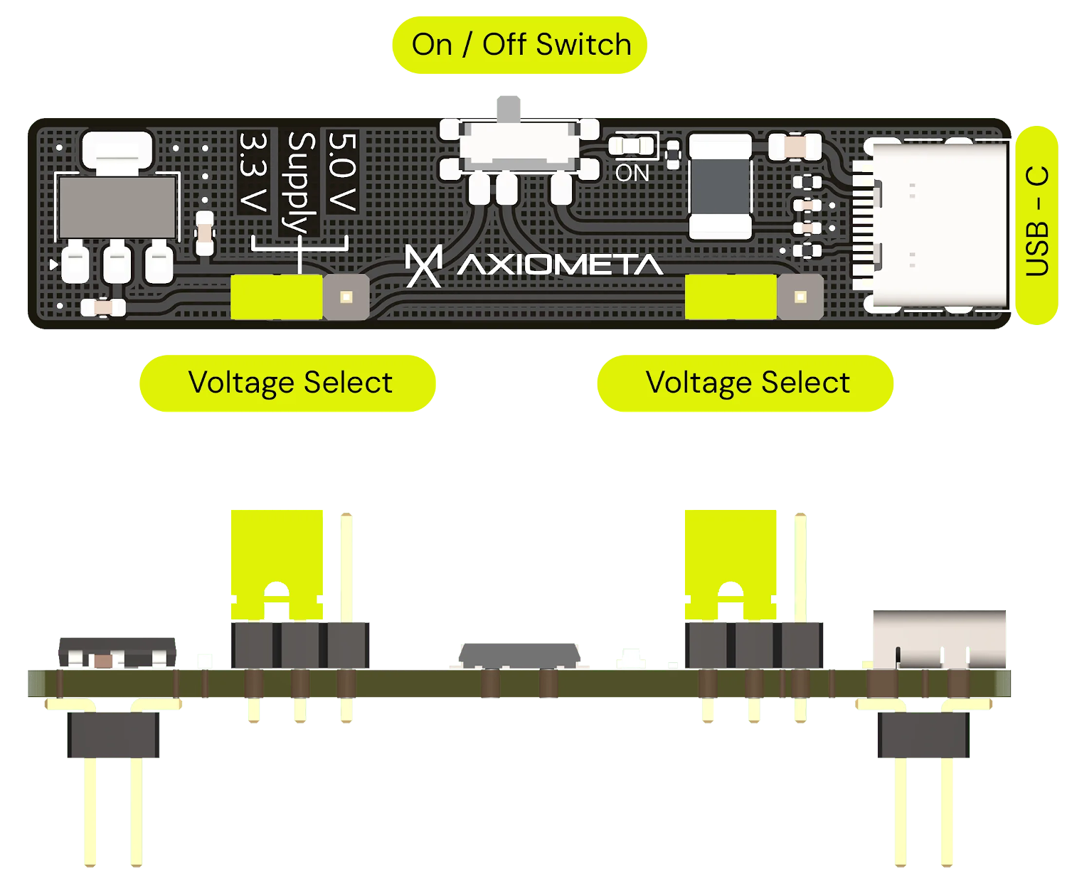 What we like about this design is how simple it is. Getting the 5 V is easy, it just takes the proper resistors on the connector’s CC line. From there, a TPS63001 and a handful of passives provide a regulated 3.3 V. As you can see in the video, all you need to do when you want to change the output voltage for either rail is slide a jumper over.
Sure, it wouldn’t be much harder to add support the other voltages offered by USB-C Power Delivery, but how often have you really needed 20 volts on a breadboard? Why add extra components and complication for a feature most people would never use?
As an aside, we were very interested to see the torture test of the SMD pin headers at the end of the video. There’s considerable debate in the world of badge Simple-Add Ons (SAOs) about whether or not surface mount headers are strong enough to hold up to real-world abuse, and apparently similar concerns were raised about their usage here. But judging by the twisting and wrenching the pins withstood in the video, those fears would appear unwarranted.


Bravo 👏 great way to supply breadboards!
i’m hugely fond of the variety of boards and chips that make it easy to connect to usb-c, microusb-a, and to charge lithium ion cells too. but for getting 5V on a breadboard, it doesn’t make much sense to me. usb-a wall warts continue to trickle into my house even as most of my devices have switched to usb-c. when i want 5V on a breadboard, i have such an abundance of discarded wall warts to chose from!
so in my mind this is basically a low drop out 3.3V regulator with a funny form factor :)
Sad thing is, that Something like this is already on AliExpress
https://a.aliexpress.com/_EHBhI5W
500ma is the limiatation of all these, they dont take advantage of usb-c.
9V would be very nice for guitar effect pedal prototyping
Yeah that’s one frill I wouldn’t mind… USB-C has all sorts of handy voltages and it would be nice to have a selector with some options
What you and Joel are looking for is called a “trigger board” or, less often, a “decoy board” . Bridge a solder pad to select voltage, put USB-c on one side and receive fixed voltage on the other. $6.06 for a ten pack. Any time a brick or connector fails in my world, I’m mounting one of these and replacing barrel and proprietary connectors with these.
Just the ticket for this kind of thing.
That seems like a nice way to get lots of buzzing from noisy switch mode power supplies.
Which most practical circuits should be able to filter out anyway. We can’t live on 9V batteries forever (:
But can it do positive ground. Old germanium PNP transistors did this and early effects so the barrel jack in it’s early days got it’s backwards polarity. Everything else is pin positive. The jack may exit a hole in a metal grounded case. Most of the early sockets were mounted behind a hole with 2 screws not a molded piece.
Old USB is trivial to get power from, there’s just always 5V no matter what. USB-C requires negotiation to turn the power on, you can’t just cut the end off a cable or whatever.
The only “negotiation” here are two 5.1k resistors on the CC lines.
I don’t think you even need that. I’ve got assorted charge-only usb-c devices that I’m pretty sure only have a two-wire cable…
(And needed for backward compatibility with usb2 usb-b devices, too. Unless. The cable has the resistors…
I saw this ptroject already, and i really dont get it. I mean, similar $.50c modules from China are easy to find, and this one offers nothing compelling over those.
I designed something similar-ish, using a small battery pack to reduce the number of wires snaking around my desk. Includes a battery pack and support circuitry (protection and charging), a physical switch, a buck-boost controller with a tracking negative rail, a 0.28″ LED voltage readout. The current provided is only a couple hundred mA at most, but that covers the vast majority of my use cases. And all the circuitry is hanging off the end of my breadboard so it doesnt obstruct any prototyping area. The battery pack doubles as a spacer to keep everything from wobbling around.
Seems like a good application to enable USB PD no? It would be nice to get a supply from 3.3 to 20V @ 2A!
Adafruit have a few products based on an HUSB238 chip, which looks to be fairly small and simple. It could work well.
Seems to me that once you negotiate 9 or 12 or 20v, getting 3 and 5 becomes moor difficult.
Does anyone know of a simple to build efficient buck regulattor that provide both 5 and 3.3 from the higher voltages with reasonable efficiency?
I have already made something along the same line a while ago. It allows you to select voltage up to 20 V. The negotiated voltage and the selected 5 V or 3.3V are both available on the board. Oh, and instead of using an LDO, I used a buck converter…
5 pieces cost approx. 6 euros (approx. 6 dollars) with shipping in Germany. And they have a 7-12V (DC) input with round plug in addition to the USB connection.
As nice as this is, it is state of the art and unbeatably cheap. Just search for ‘mini USB breadboard 2-way power module outputs 3.3V 5V DC voltage stabilisation’ at the retailer of your choice.
Yes Jon, and sadly still no one is caring about a nice 5V, 3V3, +15V-0-15V capable breadboard power supply, for being able to power Operational Amplifiers projects. Also, the 5V and 3V3 outputs are usually very weak for ESP32 running Wifi and run into brownout issues. Any new model giving 2 Amperes at low voltages and 1ampere capability at the high ones would be a true breakthrough!
Sorry, missed on the engineering. It will work as-is but I would not buy it as-is. There are several issues in the design. The one that stands out is the switch can only handle “1.0A @ 6V” so there is a mismatch with the other components, like the Polyfuse limits (1.25A). Suggestion is to add a MOSFET control on 5V to the switch or just use a header jumper to save cost.
I’ll happily use the design and modify it to match my own needs. Specifically going to thru hole materials where I can. I can CNC the board pretty quick and be up an running in no time.
May even build a variant to use with my small bench supply just to keep it neat. The way I have it now works, but isn’t always practical.
This is pretty neat and deserves the write up it got.
But can we please stop harping on how “ridiculous” and “antiquated” devices are that don’t use USB-C? It frequently seems like the editors are doing so. Just talk about how useful USB-C is instead of criticizing the other versions of USB. It starts the article off on a negative note. There are modern products that are still coming out that use other versions of USB and work perfectly fine.
No. Any “modern” product coming out that’s not using USB-C is literally antiquated, and whoever is producing it should be shamed into updating to the current standard.
That’s a ridiculous and narrow minded statement.
Not sure that’s true. Since basic USB-C support on the level of micro USB can be had with two resistors there really isn’t a reason to use micro USB anymore.
If you release something with it instead of USB-C you are just causing issues with people moving over to the newer standard.
That extra 4¢ in materials and machine time adds 16¢ to the final retail price.
But yes I agree
Neat little module. I recommend you have a look at the CANADUINO® Breadboard Power Supply module as well since it adds 12V output and USB UART to the game:
https://www.universal-solder.ca/26867
We also have a version (without the 12V) that attaches perfectly to our permanent breadboards:
https://www.universal-solder.ca/26886
“how often have you really needed 20 volts on a breadboard?” Well, you could do a few things with op amps that way, would like to have it make a fake ground right in the middle of course.