If you need to measure a distance, it is tempting to reach for the ubiquitous ultrasonic module like an HC-SR04. These work well, and they are reasonably easy to use. However, they aren’t without their problems. So maybe try an IR time of flight sensor. These also work well, are reasonably easy to use, and have a different set of problems. I recently had a project where I needed such a sensor, and I picked up a TF-MiniS, which is a popular IR distance sensor. They aren’t very expensive, and they work serial or I2C. So how did it do?
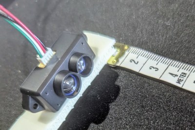
The unit itself is tiny and has good specifications. You can fit the 42 x 15 x 16 mm module anywhere. It only weighs about five grams — as the manufacturer points out, less than two ping-pong balls. It needs 5 V but communicates using 3.3 V, so integration isn’t much of a problem.
At first glance, the range is impressive. You can read things as close as 10 cm and as far away as 12 m. I found this was a bit optimistic, though. Although the product sometimes gets the name of LiDAR, it doesn’t use a laser. It just uses an IR LED and some fancy optics.
How it Works
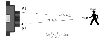
The simple explanation for how these sensors work is that they bounce light off a target and measure how long it takes to see the reflection. This is oversimplified, but one thing to keep in mind is that light is fast. To measure a millimeter, you need to measure a difference of less than 7 picoseconds. Light travels 1 mm in 3.3 picoseconds, and then the return flight doubles that.

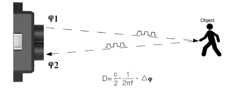
Because of practical considerations, there are typically a few specialized techniques used. A pulsed sensor turns the illumination on and off and samples pixels to determine the ratio of the overlap in the outbound beam and the reflected light.
It is also possible to sample four measurements on each cycle (that is, four measurements 90 degrees apart) and compute the distance with some fancy trigonometry. TI has a paper that goes into some detail. Or, if you prefer video, they have a video on the topic, too, which you can see below.
Practical Concerns
Of course, you can’t measure infinitesimally small times, so the sensors are typically blind when you get too close. This sensor claims to be able to read as little as 10 cm. However, if you read closely, you’ll see that if the total distance is under 6 meters, the sensor is only accurate to within plus or minus 6 cm. So at 10 cm, you might read 4 cm to 16 cm, which is a pretty big difference.
Ambient light can affect measurements, too. One thing you might not think about is that it also matters how reflective the target item is. All of these things can reduce the 12-meter range.

You also have to think about the field of view. The further away something is, the larger it needs to be. At 12 meters, for example, the target has to be at least 42 cm on a side to present a big enough target. At 1 meter, a 3.5 cm side will suffice.
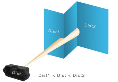
The target must also be fairly flat in the field of view. If the sensor sees a partial reflection at one distance and more reflection at a further distance, you’ll get an inaccurate reading. None of these things are insurmountable, of course.
Connecting isn’t hard. You use the red/black wires for 5 V power. A 3.3 V serial port is on the white and green wires: white is the line the unit receives data on. We’ve read that if you hook these up backwards or overvolt them, they’ll die. We didn’t test that.
Code
It is pretty easy to write some MicroPython code to get some readings. You can download the code to try it out. The heart of it is very simple:
while True:
   total_distance = 0
   valid_samples = 0
   for _ in range(NUM_SAMPLES):
      distance, strength, _ = get_lidar_data()
      if distance >= 0 and strength >= 100:  # throw out "weak" values or errors
         total_distance += distance
         valid_samples += 1                  # only count good values
   if valid_samples > 0:
      print(total_distance / valid_samples)
By default, the device sends data out frequently. If you want to change things, you can and you can even save your setup so that it will continue to operate to your last settings.
The output is two 0x59 bytes followed by the distance (two bytes), the strength (two bytes, LSB), a device temperature (two bytes), and a checksum. All the two-byte values are least-significant byte first.
Commands all start with 0x5A and the length of the packet. Then there’s a command code, any data the command needs, and a checksum. Many of the commands are fixed, so the checksum is already computed in the documentation for you.
Speaking of documentation, if you want to write your own code, you don’t really need the datasheet. You do want the “Product Manual” from the Benewake website. The commands are all in that document. You can switch to a readout in millimeters or centimeters. You can set how often the system sends data. You can also put it in a polling mode. The slowest you can get data is once per second.
In Use

So how did it work? Some informal testing on the bench wasn’t too bad. The error at near distances was within range but pretty bad at about 3 cm. However, it looked relatively constant, so you can account for it in your code. We don’t know if different materials or different sensors would require different offsets, but we’d guess they do.
There was some very small noise in the sensor output, but, honestly, not much. There were no wild results to filter out. Averaging didn’t buy much because the output was pretty stable already.
Conclusion
Like most things, this is a good solution if you need it, but there are other options, and you have to weigh the pros and cons of each method. Of course, you can build your own, which might help you optimize. Sometimes, the ultrasonic sensors are just fine.


“The target must also be fairly flat in the field of view”
Well using Femto photography principles and quantum mechanics you can technically get time of flight, around a corner and from a curved surface, and even map the basic shape of the object
Basically echolocation and radar using raytracing.
With enough light pulses, but if you want the results fast and accurate how easy can a micro chip count a few hundredth of a pico second
Using pi and some trigonometry would also mitigate accuracy problems from a non flat surface or a area that’s not level,
That’s where you want a stereoscopic system using multiple wavelength and two receivers.
Some sensors give access to the raw data, which can give some useful information about the shape: https://arxiv.org/html/2408.03838v1
Yoooo!!! Didnt think of that, thats asome amazing piece of information!
Although the product sometimes gets the name of LiDAR, it doesn’t use a laser.*
LiDAR is Light Detection And Ranging. A LASER is not at all necessary.
If I’ve learned anything from xkcd, it’s that moving mass at the speed of light, even your 1mm stroke, causes planet-wide devastation due to atmospheric heating.
Read the TI white paper that Al links to. It’s pretty good at explaining this, and comparing it with other methods. Note the date: this stuff is not new.
If you move fast enough to create a light shockwave you would produce Cherenkov radiation, with its unmistakable blue glow. Neat.
Thanks for letting us know.
Informative writeup on TOF sensors. However, don’t be too quick to jump over to the digital domain and leave the analog behind. Remember the distance measuring sensor using the “Triangulation Method”?
It holds the key to accomplishing two very important functions!
https://patents.google.com/patent/US11977391B1/en?oq=us+11977391b1
It’s Hack A Day, not Hacks A Day. You are only guaranteed one hack shared out of multiple posts. Read the TOS.
Thanks – I used to try to figure this out in my head as a student but was not sure if we can precisely measure time period that short. Or at least not without some bigger machinery. I was thinking that maybe it sends one beam and measure phase shift between sent beam and received beam or maybe even two beams phase shifted.
If you squint just right, it’s also the same thing as “modulate the light at a given carrier frequency and figure out the phase shift”. For a particularly simple way of doing the phase shift.
Very clever indeed.
Makes me think that you could use other frequency-based rangefinding tricks like putting out chirps, etc.
Is anyone playing around with this on a hacker/project level?
Laser tape measures are using phase method to measure distance: https://hackaday.com/2018/05/22/hacking-a-cheap-laser-rangefinder/
How do the Xbox Kinect ones work? Seems I recall that was some high end hardware they cancelled and you can find in a dumpster now.