As more and more of the technology that we paid for turns becomes a subscription, there’s slowly been a momentum shift in the open source world of building replacements for these intrusive rent-seekers. We see this all of the time for self-hosted media and communications servers, but now we’re starting to see it in hardware as well. The OOMWOO robotic vacuum cleaner is completely open source, from hardware to software, and requires no cloud services whatsoever.
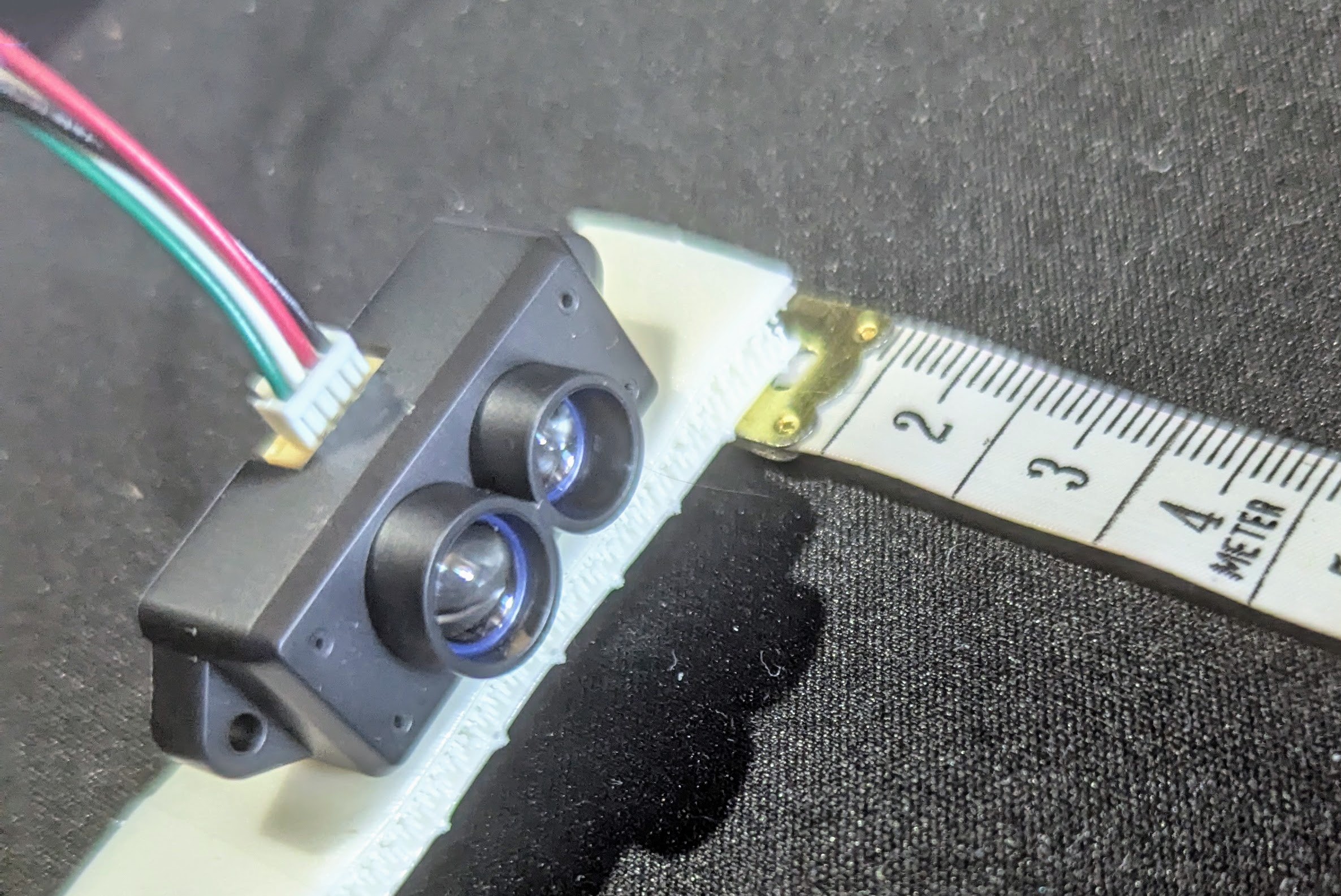
Although it’s open source, not every component is something one could buy off the shelf. It does require a 3D printer for most of the parts, but assuming that requirement is met most of the rest of the build comes together easily enough. For compute it relies on a Raspberry Pi running ROS 2 software and is set up to integrate easily with other existing open tools and projects such as Home Assistant. Like its proprietary cousins it can sense and map the rooms its placed in, but this platform uses an inexpensive 2D lidar system to keep costs down.
Right now the project is not quite complete, so we’ll all have to keep our eyes on this one as the team building it progresses. But they do have most of the software development done and the bill-of-materials is in progress. As an open project it’s being developed by many volunteers and there are a lot of areas available to contribute to as well, all currently set up on the project’s GitHub page. Right now many of those areas of effort are adapting the 3D printer files to off-the-shelf parts.
With the rocky status of the Roomba ecosystem, projects like this are more important than ever.