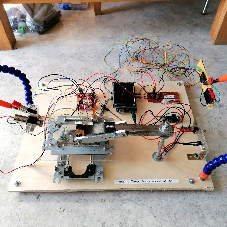
Doing it yourself may not get you the most precise lab equipment in the world, but it gets you a hands-on appreciation of the techniques that just can’t be beat. Today’s example of this adage: [Stoppi] built an atomic force microscope out of mostly junk parts and got pretty good results, considering. (Original is in German; read it translated here.)
The traditional AFM setup uses a piezo micromotor to raise and lower the sample into a very, very fine point. When this point deflects, it reads the height from the piezo setup and a motor stage moves on to the next point. Resolution is essentially limited by how fine a point you can make and how precisely you can read from the motion stages. Here, [stoppi]’s motion stage follows the traditional hacker avenue of twin DVD sleds, but instead of a piezo motor, he bounces a laser off of a mirror on top of the point and reads the deflection with a line sensor. It’s a clever and much simpler solution.
 A lot of the learnings here are in the machine build. Custom nichrome and tungsten tips are abandoned in favor of a presumably steel compass tip. The first-draft spring ended up wobbling in the X and Y directions, rather than just moving in the desired Z, so that mechanism got reinforced with aluminum blocks. And finally, the line sensors were easily swamped by the laser’s brightness, so neutral density filters were added to the project.
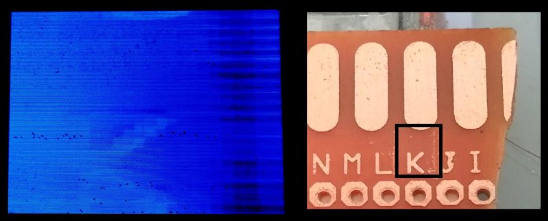
The result? A nice side effect of the laser-bouncing-off-of-mirror setup is that the minimum resolvable height can be increased simply by moving the line sensors further and further away from the sample, multiplying the deflection by the baseline. Across his kitchen, [stoppi] is easily able to resolve the 35-um height of a PCB’s copper pour. Not bad for junk bin parts, a point from a crafts store, and a line sensor.
If you want to know how far you can push a home AFM microscope project, check out [Dan Berard]’s absolutely classic hack. And once you have microscope images of every individual atom in the house, you’ll, of course, want to print them out.


Hello! Here you can find a short video of my AFM on YouTube 😉
https://youtube.com/shorts/Vr66sw34qPI?si=VQf4NmhgJgbSrlss
Surely it must be not difficult to get substantially better than 35 um resolution. The absolute bargain basement dial indicator easily resolves 25 um even on a bad day. A midrange Starrett electronic is good to 1 um. AFMs are famous for resolving single atoms (so, 10 000 times better than this, 0.0001 um)
So what’s the actual resolution of a setup like this? What’s the limiting element?
The intention of my project was to create the most inexpensive emulation of an AFM while retaining the essential components such as the cantilever, laser, and graphical representation of the surface on a screen. Keep in mind that my setup only costs about $65 in total. The resolution could certainly be increased, but the x/y resolution must match the z resolution. Therefore, it doesn’t make sense for me to use piezos with nanometer resolution for the x/y adjustment and a comparatively thick compass tip. My line sensor also has very large pixels. This, of course, also reduces the resolution. I don’t really understand why my setup, designed for schools and made from everyday parts, is being compared to commercial AFMs that cost 100 times more. From the outset, my implementation was intended as an extremely simple and cost-effective option for schools or student projects…
The only improvement I can think of would be some cheap, abundant, and of varying geometry, higher resolution tips; record player needles (something similar to these, 3@ $8: https://a.co/d/9mwMjAw )
Hello! Thank’s for the hint with the record player needle. This could indeed increase the resolution. But one of my problems was the twisting of the tip on edges. So the cantilever has to be very stiff around one axis to avoid twisting…
The difficulty is somewhat engineering, but mostly cost. AFM tips are really expensive easy to drop and unfortunately break. Piezo motors also really expensive. This build is really really cool. It’s establishing a baseline for how to use these principles with junk around the house!
Also once you go lower than this by an order of magnitude or three tiny vibrations become big problems. We had to put our afm on sand on granite slabs and when runs were in progress no one could open or shut doors etc. walking near the instrument would raise angry eyebrows even when it wasn’t being used.
I can just imagine using an interferometer to measure the laser deflection. A magnetic floating table is a tempting build, it would be nice here, there’s a lot of traffic.
If you can make an interferometer from scraps I would be real impressed. Alignment is real tedious even with all the screws and precision mounts.
Indeed, for a ‘around the house build’ ruby/diamond record player needles would do the trick to increase resolution and possibly reduce lateral motion.
Just to clarify, Dan Berard’s microscope is a scanning tunneling microscope (STM) rather than an AFM. AFMs measure the deflection of a cantilever beam whereas STMs measure tunneling current.
It’s quite Evident
That was my bad. Thanks!
I wouldn’t worry these devices are each very niche. Mostly only analytical chemists who specialize in surface analysis know about them well. Physicists do too but they have to know about everything
Are you sure this is AFM? It looks more like running a stylus over a surface. It is hard to see how the electrostatic forces between atoms are deflecting that huge spring. Or that it is being moved up and down with feedback of the field strength between the probe and the surface. Just curious. The project linked in the text looks the same.
I remember a few years back there was an electron microscope build posted here on HaD, it used a few piezoelectric elements soldered together to make fine manipulations.
I wonder if the electromagnetic focusing from the dvd drives could be used, mounted at an angle, like a high precision galvanometer. Maybe using an image sensor from a mouse or a webcam with the focus brought as close as it’ll go, so it acts as a microscope, to view very small deviations in the needle position.
I am totally agree here an attempt to build AFM https://hackaday.io/project/191403-atomic-force-microscope-from-ground-up
@Lightislight: I have built several very simple interferometers f.e. using parts of old DVD drives like Michelson, Mach-Zehnder, Jamin…
https://stoppi-homemade-physics.de/michelson-interferometer/
https://stoppi-homemade-physics.de/mach-zehnder-interferometer/
https://stoppi-homemade-physics.de/jamin-interferometer/
Sorry to be a party pooper but this is not AFM. It’s a sensor that get thickness using laser and photodiode. AFM senses surface by van der waals force. This metal thing is too big to be moved by the laser. Metal tip scratch the surface and photo diode reads it’s height. AFM should get you to sub-nano domain not mm. Don’t get me wrong it’s amazing machine but it’s not microscope. Please take a look at https://hackaday.io/project/191403-atomic-force-microscope-from-ground-up
Hello Eduard! Thanks for your comment. As I mentioned above it should be a simplified model of an afm but with the main characteristics. Many AFM’s work in contact mode and use a laser, photodiodes and a tip at the end of a cantilever. Therefore I think that my solution isn’t really miles away from a real afm. Your attached awesome afm uses a different method, the change of the oscillation-frequency due to interaction between the tip and the surface. This method seems to me much more complicated for being realized with minimal efforts. Therefore I choose the contact mode for my project…
I still clearly remember a project like this was on the German science show Quarks&Co in the early 2000’s, where they presented a hobby project to build a Scanning Tunneling Microscope. This one was also based on piezo element.
I was amazed what they could do with stuff reachable for the hobbyist.
The project website is offline, but can still be viewed on archive.org.
https://web.archive.org/web/20070623190944fw_/http://sxm4.uni-muenster.de/stm-en/
Hello! I have done that project 20 years ago and made some changes to run this STM with arduino:
https://stoppi-homemade-physics.de/rastertunnelmikroskop/
Hi, Chris, thank you very much for sharing. We also build an AFM but currently have issues on AFM tapping amplitude drops to zero once click scanning, would you have any insights on the reasons?