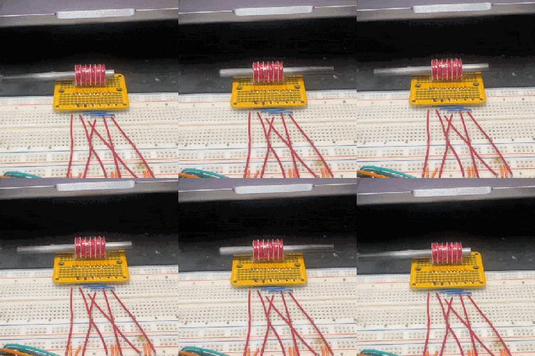
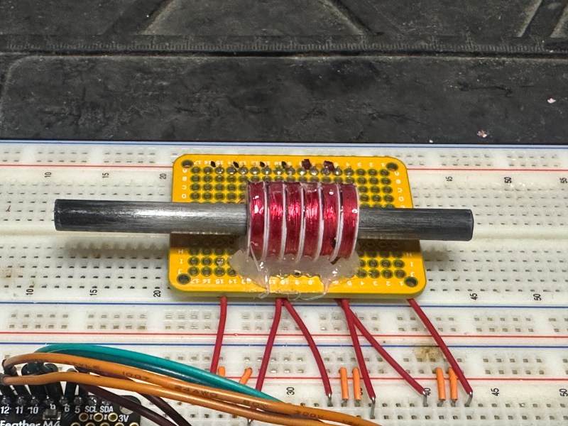
We’ve seen plenty of motor projects, but [Jeremy]’s DIY Tubular Linear Motor is a really neat variety of stepper motor in a format we certainly don’t see every day. It started as a design experiment in making a DIY reduced noise, gearless actuator and you can see the result here.
Here’s how it works: the cylindrical section contains permanent magnets, and it slides back and forth through the center of a row of coils depending on how those coils are energized. In a way, it’s what one would get by unrolling a typical rotary stepper motor. The result is a gearless (and very quiet) linear actuator that controls like a stepper motor.
 While a tubular linear motor is at its heart a pretty straightforward concept, [Jeremy] found very little information on how to actually go about making one from scratch. [Jeremy] acknowledges he’s no expert when it comes to motor design or assembly, but he didn’t let that stop him from iterating on the concept (which included figuring out optimal coil design and magnet spacing and orientation) until he was satisfied. We love to see this kind of learning process centered around exploring an idea.
We’ve seen DIY linear motors embedded in PCBs and even seen them pressed into service as model train tracks, but this is the first time we can recall seeing a tubular format.
Watch it in action in the short video embedded below, and dive into the project log that describes how it works for added detail.


I’ve also been very interested in these motors and finding it hard to find information to DIY the controller. I found the same paper Jeremy used for the physical construction of the motor, but it’s hard to find a mature controller that will drive them. Any bldc motor driver with feedback should be able to do it but modifying the code for a linear motor with end stops is a bit beyond my skills. If anyone has any pointers in this direction I’m all ears!
Pls look into Iris dynamics linear actuators.
There is a saying “No Pain No Gain” In 2025 (if this is when you asked this question) apply some “pain” $$ for Grok/Claude/ChatGPT or use WhatsApp AI or Gemini on a mobile phone and you will be supprise how helpful they can be.
Really cool! Linear positioning is always such a pain. I wonder what the accuracy and precision is for this type of design? The nice thing about mechanical approaches is being able to gear down the throw. The bad thing about mechanical approaches is having to gear down the throw.
It’s a cool demo, but the bad thing with this design it basically useless for most applications, since any force without applied power will move the bar, and will push directly against the magnetic force. A stepper with a worm gear have its benefit. The resolution will also be low, even with micro stepping, since its about coil size and magnet spacing. Once again a stepper with gearing have way more resolution.
Ah yea I see, I for some reason presumed this had hold power like a stepper. Ultimately I agree, and mostly use worm drives for linear motion. Oh well It’s still a cool take on a solenoid!
Try PID
Valve lifters usually use a 90 degree actuator turning a linkage with a set throw. Set the 0 volt position at the fail safe position, normally closed or open valve stem position, 10v at the opposite. Honeywell 1020s have a 1.75 inch throw. This would allow a position resolution of 4.45 micrometers with millivolt signals. Not much travel, but exceptionally robust, can handle twelve pounds steam on a six inch line for decades. 72psi on that little bar is going to back emf those permanent magnets right out the brackets.
It’s zero cogging, and precision is essentially limited by your position encoder. Nippon Pulse has been making these for years, and claim 10 nanometer precision.
In theory yes, but in reality no. The physical design of the motor and the drive circuitry matters a lot too.
It is just like with stepper motors, yes if you could drive the could precisely enough you may manage high precision but it is still limited by the design of the motor and drive circuitry, micro stepping lets you get smaller increments but it isn’t as stable.
Looks like the voice coil motor in Canon lenses https://www.canon-europe.com/pro/infobank/usm-stm-lens-technology/
It would be an interesting challenge to arrange coils/magnet polarity to not only have differential positioning along the Z axis but azimuth/rotation as well.
If space isn’t a concern, you could just devote a different section of the rod to rotation with a separate set of coils/magnets. You could even use a conventional motor driving the rod through a set of splines, like the drive shaft on a RWD car.
Check out the work by Iris Dynamics in Victoria, BC. They have built a wide array of actuators and drives based on exactly this technology! http://www.irisdynamics.ca
🤔
uh… a geared actuator will hold position without power. take the power off of this and the rod just slides
A good one won’t.
You know, ball screws, servos, velocity feedback etc.
Outside the stepper motor ghetto.
I’ve done this with a single coil. The trick is to embed the magnets at the ends of a roll of sheet iron all in the same direction. What that does is, the coil attracts the iron regardless of the direction of the current, but repels or attracts the magnets depending on the polarity.
So, you drive it with a H-bridge and flip the current around in a 50/50 duty cycle at some relatively low frequency: the magnets get equal repulsion and attraction on average so they’re not going anywhere, but the iron draws to the middle so the bar is centered. When you change the duty cycle to, say, 20/80 then the magnets are pushed more to one side with greater force acting against the centering force from the iron until they balance out.
Turns out, when you get the geometry more or less right, it responds quite linearly to the duty cycle, moving the bar in and out of the coil in both directions. It doesn’t have any holding force because it’s balancing where the magnetic fields cancel out, but you can position something like a mirror or a point of a needle etc.
I tried to do something like you, with single coil but with position sensing. Would work like a servo with resistive sensor, could have pretty nice force even at zero position. Dropped due to severe lack of free time.
https://hackaday.io/project/19547-electromagnetic-linear-servo
If you ever re-visit it, here’s a tip: LVDT
You have your one driving coil. You cap it with two sense coils at either end and wire those in series anti-phase to each other. When the bar of iron is centered, the induced voltages in the sense coils cancel out and you get zero output. When the bar of iron is offset to one side, the amplitude of the induced voltage increases and the phase relative to the driving current flips around depending on whether you’re going left or right off the center. Basically the voltage output is the same polarity going one way, and opposite polarity going the other way, relative to the input voltage.
The tricky part is measuring the output voltage. You have to synchronize your measurement to the current flips, which is tricky to program if you’re using something like the hardware PWM of an Arduino. Or, you can do some sort of analog magic to rectify the pulses and low-pass filter it to get a steady output, but that will make your control loop slow and less stable.
Thanks for idea! I thought about similar solution – just one smaller coil on whole length. It would work like variable core transformator, voltage in output coil would depend on position of plunger. It was not bidirectional, so no need for two coils on both ends.
The only issue with solenoid type actuators is that they’re generally very feeble and not efficient. The magnetic field is like a very soft spring against the iron core. Even with feedback, your force is proportional to the difference between where you’re driving it to and where the plunger actually is, so you’ll see diminishing results at the far ends of the actuator travel.
The further out the magnets or iron are from the center of the driving coil, the weaker the pull. There’s an inverse square or cube law at play, or maybe it was even to the fourth power of displacement, I forget the details. That’s the main reason why you don’t get very long travel out of a solenoid actuator. Millimeters = strong, centimeters = weak.
Fro those interested in direct linear drives, you might find some inspiration in the paper “Modular hybrid linear and surface stepper motors” by Viorel, Szabo and Dobai. Web version here:
https://users.utcluj.ro/~szabol/Research_Results/Modular_hybrid_linear_and_surface_stepper_motor/Modular_hybrid_linear_and_surface_stepper_motor.htm
This makes me think of indecent things…
I can be some very interesting applications to this kind of motor in the movies industry.