Modeling a railroad is hard. Railroads are large, linear pieces of civil engineering. So many modelers are drawn to the smallest scale they can use. Recently a new scale, named T, at 1:450 has been pushing this barrier. But fitting a reliable mechanical drive mechanism and MCU board in a package this size is a challenge. In practice, even more of a problem is getting reliable electrical contact through a metal wheel on metal track (about the worst possible design for a contact).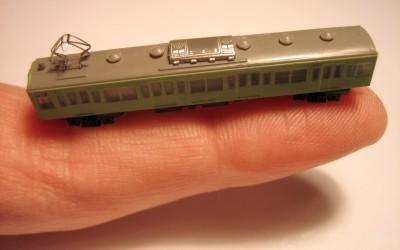
T always seemed to us a long way out on the bleeding edge. But all that may have changed. In a recent Hackaday.io writeup, author [Martin] describes a PCB technology based linear motor system to externally drive T scale locomotives.
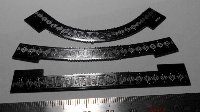
The system uses 4mm planar coils. The underside of the PCB has another coil, so the effective pitch is 2mm. With microstepping, a step of 0.25mm is possible, and trains run smoothly. Current is 3-400mA.
Since the system also guides the car, actual ‘track’ is unnecessary, and [Martin] is using printed paper covering rather than 3D track. Items like autos and boats can be automated as well. Modelers in larger scales might well use it for automated pedestrians and such.
Also an advantage, all cars are powered, so coupler reliability is a reduced issue.
This feels like it could be used for many things, far beyond model railroads. It’s an option for any time you need to move a few mm scale object in 2D.
Image courtesy David K. Smith, CC BY-SA 3.0


Kudos, this is really cool.
It’s pretty much the same system as Teeny trains.
I think it’s the same approach used by miniaturewunderland for their Monaco gp track.
A huge difference in complexity and performance though. While I have thought about doing a racing car layout with mine, it would be functionally equivalent to a traditional slot car set – just two lanes with one car each, using the existing track and controllers with some new software to handle the racing side of things. Wunderland’s system has multiple cars per lane which can run at different speeds plus sideways movements – something like 500 individually controlled 2-axis sections. However, if they were willing to compromise some of the features, they could simplify things a lot.
This is impressive!
If you have a pcb anyway, you could integrate all the electronics for driving each segment on the underside. Just run a power and data bus to each section.
How would the 40 cars that get pulled follow a curve? Or is that meant as a strength test?
Just give each car a magnet and let them follow each other. And then break up trains and reassemble, or make them crash
There are many design tradeoffs at work here, some from the electrical side and some from the model railway design side, coming down in the end to flexibility and cost. Power sections are typically a dozen or so track pieces in length, so you would need 1 active piece for every 10 or passive – twice as many board types, or all pieces being larger and able to do either job, or build it onto the joiner boards, etc. Other switched sections are only an inch or so long, or have to be very narrow (bridges, turntables, etc). Some projects, especially with roads, do not have any switching at all with the whole track permanently powered for continuous streams of traffic. Other custom sections need polarity reversal or other non-standard features. Having one universal set of track pieces and just plugging cables into a plug-board keeps things manageable.
Every vehicle is self-propelled and not coupled to its neighbors. They all simply move in synchronized formation, with the loco not actually pulling anything. That allows unlimited length trains, tight curves, steep gradients, etc. Trains can be broken up and reassembled by stopping them over a section break then turning one section off. Part of the train can then move off by itself. I generally try to avoid crashing them, though that does happen if a hair or piece of grit ends up on the track.
Since you have the whole track linear motor, next step… tiny scale maglev train?
The “lev” part of maglev is the difficult bit. The propulsion force is quite small and relies on the magnets touching the track to minimise losses. Additionally, the magnets and coils are set to attract one another, not repel for lift.
Of course, the real thing flies at an altitude of around 4 inches, so when scaled down 500-fold a tiny model would not actually have to levitate. I have run this at scale speeds of 200kph or so and could push it faster, but my model-making interests tend to lie with older trains.
Next step to increase the train speed until it can become inductive rail gun potential.
Do you have to balance or calibrate the individual cars to match? Or are bulk magnets consistent enough, and the weights small enough, that it just doesn’t matter?
Not as such. There have to be enough magnets for the weight, which isn’t a problem with plastic models at this scale. One thing I do have to tweak is to make sure the underside of the model is smooth enough, with no rough edges that can catch on the track and cause hang-ups. With new models, I run a string of them spaced a fixed distance apart for ten minutes or so. If any come off or drop back in position, I trim off a bit more plastic.
I’ve been thinking along similar lines for a while myself, and have some T gauge layout that maybe oneday I’ll be able to get out and finish. Seemed to me like a good way to be able to drive even the tiniest trains – that little branch line/shunting locomotive can obviously be pushed by a carriage but its much nicer if you can run them independently.
This gets away from the trickiest challenge with motors on such a small gauge – getting all the motors to work similarly fast, in a longer T gauge train if the rear motor units are just that little bit too high in rpm they can often force a derailment as the grip to the rails the little magnet wheels give is actually remarkably high with not a huge amount of weight to tip. (a problem that gets worse with voltage drop off further from the power in long trains, and with their scale is damn near impossible to control electronically – just no space inside unless you wish to bond an entire train into one long chain permenantly)
Has to be said for the most part the little motor units do just work fine and you can get pretty long trains cruising around with few issues, so don’t be put off from trying it if you are interested – in my playing around the worst thing is trivial to overcome – a dirty track, what a shocker when at scale a spec of dust is getting on for a rather large branch/rock and the contact area for power transfer is so tiny.
I built and exhibited a medium-sized conventional T Gauge layout a few years back (Sarum Bridge), and my frustration with its limitations is what started me down this path. I ended up with 3 trains each with 3 motor units permanently wired together, and even that was struggling by the end of a 3-day show.
I have now progressed far enough with the linear motor approach to be able to handle most model railway tasks, from excellent low speed starts and stops, to automated shunting, to level crossings with road vehicles stopping for the trains, to working turntables, to horse-drawn vehicles, to even smaller 1:720 scale trains… and so on. I don’t plan to go back.
Oh I don’t blame you – there is a reason I’ve been considering it myself, IMO its the most logical solution.
But its unfair to say the standard T off the shelf motor units are not really quite good, so you can have great fun building your scale city, bridge, forest, mountain – whatever floats your boat and just enjoy running it. This magnetic drive system can always be fitted later if you feel the need, but there isn’t a need for it to enjoy T, that just required a liking of model railway and good enough eyesight.
Please don’t get me wrong – I was and am impressed by conventional T Gauge. Cramming a mechanism into such a tiny model and getting it to work acceptably is an achievement. It is just so very difficult to go beyond the basics and do any elaborate modelling with it, especially in comparison with what the larger scales allow on a routine basis.
Oh I agree entirely, from the electrical and mechanical point of view its trickier than larger gauges, though it also lets you do things you can’t do in other scales at all, the sort of elaborate modelling that will really appeal to some while being easy enough for the stock T stuff to run.
I mean things like the many longer viaduct – Welland? for instance (think that is how its spelt and the one I’m thinking of) brick arches that are supposed to be varying very slowly in height and pretty damn tall even at the shortest points, while being around 1Km long! You can’t even come close to modelling that railway architecture or environment convincingly in other scales as even the exhibition halls your model railway show/club might have aren’t big enough to show enough of it, where in T even though you’d have to play with perspective, take some artistic liberties over pure scale model mostly likely on something that big you can create a much more convincing facsimile…
To save you the effort, Z scale, which is as old as Gen-X, is 1:220 scale so this is a tiny bit less than half the size of Z.
Now my experience is cost scales exponentially with smaller size, so if a HO gauge loco is $200 and a Z loco is $400 then a self propelled T scale loco would be $800?
Nah, cost scales the other way. Scale 1:1 costs more then the salary I’d earn in my lifetime and smaller gets cheaper.
Smaller scale uses less material, so should be cheaper, but at some point economy of scale becomes a mayor factor. A “popular” scale will become much cheaper then other scales, simply because more of it is produced.
But in this world there is a big caveat. The correlation between what it costs to make something, and what you have to pay to obtain a product is completely lost. Sometimes you buy a quality product for EUR 5, another time you buy something for EUR 50 and it turns out to be worth junk not even worth the shipping costs.
T is usually very much cheaper than Z – as Z has enough size to model all the running gear, valves etc with some accuracy so its full of very specific to each locomotive and rolling stock detail parts that you just don’t get in T because you’d need serious magnification to see if it was there or not, so its just not there and the same parts can be used on most wagon and locomotive, and there are less tiny moving parts.
With tiny models, the cost of materials is a minor contributor. Production quantities, quality, detail level, etc. are much more significant. Z models are certainly more detailed than T, and as a result their locos cost about double. Carriages, track, etc are about the same for both.
Since we’ve invoked the…
ICP: “Magnets”
or if you prefer
Col J. O’Neill: “Magnets!”
Then why bother with horizontal, crank up the juice, lets have layouts on the wall, layouts on the ceiling.. layouts… innnn…. spaaaaacccceee.
Also since it’s so compact then recreating the shunting yard computer featuring as a plot device in Deighton’s “Billion Dollar Brain” should be a doddle, for extra credit, make it play Tetris :-D
“actual ‘track’ is unnecessary” rather defeats the purpose of a model ‘railway’ ? Interesting technology for sure but I like wheels on rails, visually and audibly, and I like to see at least some detail. Z small enough for me
The comment about boats and cars caught my eye..
For my OO gauge layout I want a small canal section with a moving narrow boat. These move at 4mph, so would this system move slow enough to model that?
The slowest sustained speed I can achieve is 2.5mm/sec which works out to 2.7mph in T (1:480), or less than 0.5mph in OO. I usually run my canal boats at the correct 4mph, but sometimes at a racy 5mph!
Unfortunately, a OO canal boat is much too heavy for the system as it stands. It would need a complete redesign with much larger coils and magnets with the resulting high power levels and heating problems. More like industrial automation than hobby electronics.
However, there are other alternatives – you might want to google for “St. Catherine’s Lock Shalford” and “de Graffstroom model” to see some very nice examples of working model canals in that scale.
Well are you modelling an era where the boats have motors, because you could go oldschool and have a horse on the towpath pulling it… just splatter a black ant with a bit of white paint and everyone will think it’s palomino pit pony.
Oddly enough, I have considered that. You can buy model animals in that scale (no need to capture and train an ant), and if I use a single bristle from a brush as a towrope… Of course, the boat would be pushing the horse along, and the tow path would have to very carefully positioned to match. One of many little experiments on my list of things to try.
FWIW, the new layout I am currently building is set in 1913 and has moving horse-drawn road vehicles. Not totally old fashioned, though, as I do plan to include a few of those new-fangled motor cars and omnibuses.
See that’s why I have to avoid getting too deep into modelling, because then I’d have to photographically reduce and acid etch some tiny little “strandbeast” mechanical legs for all the horses, so they’d actually look like they were walking.
Its been done – though at T gauge you can get away with simply loose pinned legs easily, so they have a bit of wobble as they travel, that looks aright at Z, though at that gauge I have also seen cam driven horse walking attempted mostly successfully.
So we finally get the WEDWay people mover? What took so long?
How difficult would it be for me to layout a PCB for a larger scale? (I am an experienced PCB Designer).
Large scale it’s probably less about difficulty and more about PCB cost per acre.
So where are the design guidelines/rules regarding the PCB design?
That would be straightforward in some respects, but quite challenging in others. I have gone through quite a few iterations to get things to where they are now, with a lot of lessons (painfully) learned.
I did my first trial version, some simple straight tracks and joiners, by hand in Eagle, and it worked fine. However, it was hard to make changes and form into curves. Instead, I wrote a program that read an input script describing the coil parameters and track geometry, and generated an Eagle script to create a complete track piece – a much better approach.
The basic coil design is straightforward, but interleaving them into a working motor is more interesting. You need a repeating pattern of 6 coils (3 strings of coils alternating top and bottom). The coil spacing must be constant at 2/3rds of the magnet spacing, with quite tight tolerances, which imposes annoying length restrictions on each piece, plus fit issues on curves. You could go for a simpler one-sided non-interleaved design, or drive the phases differently, but each of those would double the effective step size which has huge impacts on smooth and slow-speed running.
Joining the track pieces and compensating for the missing coil at each gap, is another fun bit. I am still not entirely happy with my solution to this, which involves additional joiner boards spanning each gap underneath the track, but it works and isn’t too hard to manage.
Finally, moving to a larger scale is a whole new challenge – power and heating issues raise their ugly heads. I optimized for T Gauge as the sweet spot, and even then went all-out to minimize the resistance per meter and soak off excess heat. The magnetic flux from the 4-turn coils is very low, requiring powerful magnets to compensate. To handle heavier weights, you would need more turns and larger coils, which would also allow larger (but fewer) magnets, and/or higher currents. Heat dissipation per meter rises as the square of the number of turns, and if you also crank up the current then with the square of that too. Effective drive strength / model weight only rises with the first power of each of those.
I have a Gauge T-train track but would like to replace the propulsion system with your magnetic tracks. Can you help me with my project please?