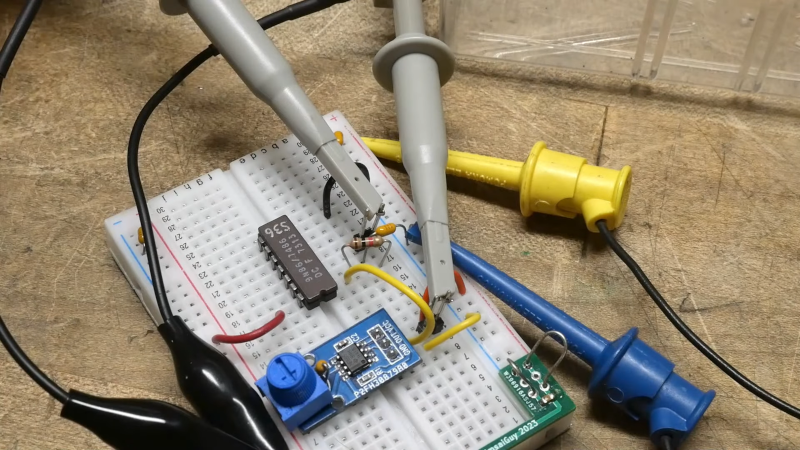
[IMSAI Guy] grabbed an obsolete XOR gate and tried a classic circuit to turn it into a frequency doubler. Of course, being an old part, it won’t work at very high frequencies, but the circuit is super simple, just using the gate and an RC network. You can see a video of his exploration below.
The simple circuit seems like it should work, but in practice, it needed an extra component. In theory, the RC circuit acts as an edge detector. So, each edge of the input signal causes a pulse on the output as the second input lags the first.
That sounds good, but it looked terrible on the scope until a 1K resistor tied to the capacitor shifted the bias point of the gate. In all fairness, the original schematic used a Schmitt trigger gate, which may have made a difference had one been available. There were slight differences, though, depending on the type of device. An LS part, for example, didn’t need the extra resistor.
Of course, an RC network is just one way to delay the input, and the delay determines the width of the output pulse and constrains the input frequency and duty cycle. However, you could use other gates, including the other XOR gates in the package to realize a fast delay.
Frequency doublers are very common at microwave frequencies, but they don’t work in the same way. There are several ways to do it, but a common method is to use a nonlinear element to generate plenty of harmonics and then filter off everything but the second one. Or the third one, if you wanted a tripler instead.


IMSAI Guy is the best. I love seeing him demonstrate a new chip every day.
Circuits like this do work, sort of, most of the time. It’s usable for a quick hack and experiments, but it’s not something you can rely on for bigger production runs, such as selling kits. The reason is that the logic input thesholds are not very well defined, and as a result, the circuit may misbehave when used with a different batch of IC’s, or IC’s from another manufacturer. Just like relying on the Beta of a BJT, it’s not good design practice.
Yes.
Absolutely.
“Circuits like this do work, sort of…” […and–sometimes…]
“…it’s not something you can rely on…
…it’s not good design practice.”
It’s never good design practice to build a digital logic circuit / system–on which the deterministic, highly repeatable operation of the system depends–using discrete reactive components.
This is the reason one does not find monostable multivibrator ICs (e.g., the 74xx121; 74xx123; 4538B) nor SE/NE555s in the basic-system design of mission-critical, or life-critical, digital designs.
Yeah the schmit trigger is very inportant .. by no means “might be”… goofy to leave that out .
XOR gates make nifty oscillators too, from AF to HF. PotatoSemi (yes, potato chip) makes GHz speed 7400 series equivalents. It would be fun to see what logic at such levels could make possible for RF.
I spent a week chasing this for fun on my bench because i didn’t have the components to make a PLL.
xors and a buffer for edge detection.
now you have pulses,
wired to an RC timer,
run that to another buffer
now you get a nice digital pulse…
then run it through a FF, to get a nice square wave…
and you’re back at the same frequency you started at…
lol
You can use a 74122 to construct a very clean pulse. That is probably how it would have been done in the day.
There’s a better way – use the remaining ’86 gates as a delay line to get clean and predictable output pulses. That was a standard circuit some decades ago, often to be found in data separator and clock recovery circuits.
One way to make this more predictable is to add a precision comparator. https://www.eetimes.com/simple-logic-circuit-doubles-input-frequency/