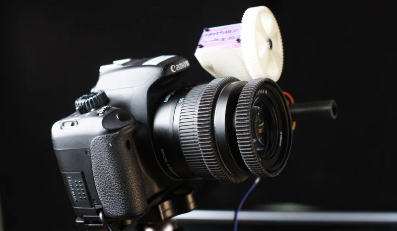
When you watch a movie and see those perfect focus switches or zooms, the chances are you’re not seeing the result of the cameraman or focus operator manually moving the lens controls. Instead, they will have been planned and programmed in advance and executed by a motor. If you take a close look at many lenses you’ll see a ring that’s more than just extra knurling, it’s a gear wheel for this purpose. Want to experiment with this technique without buying professional grade accessories? [l0u0k0e] has you covered with a 3D printable focus zoom motor accessory.
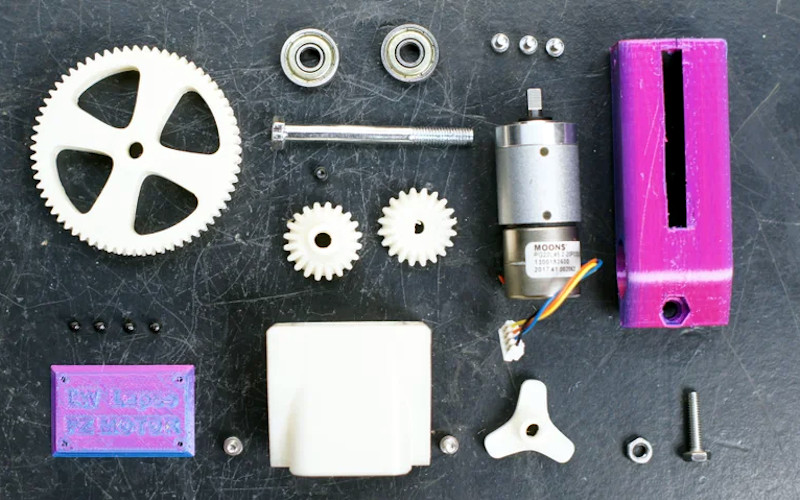
The motor behind it all is a geared stepper motor, and there are a set of printed parts to complete the model. It’s recommended to use PETG, and nylon for the gears, but it would work in PLA with a shorter life. It’s designed to work with the standard 15 mm tube you’ll find on many camera rigs, and while you can write your own Arduino sketches to control it if you wish, we’re given instructions for hooking it up to existing focus drivers. The model is on Printables, should you wish to try.
This is by no means the first focus puller we’ve seen, in fact you can even use LEGO.


I wanted to do this not for focus but for Zoom. My lenses have motorized focus control, which is common. What is not so common is motorized zoom control. I guess, I can simply adapt this for that.
Cute thing to play with. It would be a much more useful tool (i.e., actually programmable) if it had a home or limit switch — a very easy thing to add though. The OP says this is a test system, so fair enough.
I don’t get what people have with these large spur gears when one can achieve far less stick-out using bevel gears and a pancake stepper motor underneath the lens, with a miniature bearing pushing up against he back side of the bevel gear collar and the ability to attach the motor plate to the tripod mount.
The published design uses bevel gears.
Not as the ring gear around the lens
Really not sure how bevel gears would be any advantage here. I have two professional versions that add less than 15 mm to one side of the 90 and 100 mm diameter lenses, and have no bevel gears… All three motor axes of each one are parallel to the lens axis. (The three motors control aperture, zoom, and focus).
I thought that’d be self-explanatory. One can reduce the pressure angle below 20°, but the pressure line still won’t be tangential. So at least dynamically there will be a radial force component pushing a spur ring gear sideways. The switch from spur to bevel ring gears rotates the force direction by 70° to 90°, allowing the ring gear to be pinched between bevel pinion and a miniature ball bearing.
Granted, this still requires the lens to counteract a tangential force vector, but you can 3D print the bevel gear variant and get away with a flimsy construction that could bend and let spur gears skip.
First you state that bevel gears have the advantage of “far less stick-out”. Then when challenged with a commercial counterexample you pivot and say that actually the advantage is the pressure angle is in a different direction.
Paul, you’re not challenging anything here. I knew right at “The published design uses bevel gears.” that you were going to be annoying, but I played along. Don’t like a comment, don’t engage with it. My proposed design still delivers lower stick-out if you leverage that, but you seemed not to get the kind of geometry that was implied.
Goodbye.
It’s a canon lens, with its own focus motor – You can control the focus over USB…
“PLA with a shorter life”…
Honestly, I expect the only bit on this that really gets worn away at is the place where the input gear fits on the D shaft of the motor. Involute gear teeth are a rolling contact and don’t wear much, the housing shouldn’t be getting worn down at all… I suspect even from PLA this could last “forever” (excepting hot environments which would warp it) if you used a proper shaft coupling (of metal, either a flange or hub type which adapts from a D shaft to a 4 screw pattern or some means of clamping two metal plates either side of the D) instead of pushing a D shaped printed hole on to a D shaped shaft. You might also do better if you clamped a print on to the camera lens’ splined ring (splines aren’t always true involute teeth) and used the outside of that clamped together print as a gear tooth to mesh to your plastic gears rather than meshing printed gears directly to the camera’s (possibly not involute toothed) ring.
Slight correction, when you watch a movie and see those perfect focus switches or zooms, the chances are you ARE wathcing a human at work! One with years of experience, and possibly a few practice tries, suggesting otherwise is doing them a great dis-service. There are some specialised applications where the movements are pre-programmed such as high speed, or precise matching of an already shot clip. The vast majority are pre-planned not pre-programmed.
A lot of the time these days they will be using a remote focus unit not entirely dissimilar to what’s shown here, but very definitley under manual albeit wireless control. There are some systems that are getting used more and more which do offer automatic focus control, but they’re only just starting to be trusted for the most demanding of shots.
I’ll leave this The Marmalade behind-the-scenes clip here, with their “Spike” robot for slow-mo shots.
https://www.youtube.com/watch?v=A2CLQdCU7O0
I was wondering why it has that rather large gear which makes the thing so bulky and then thought about how you design a reduction system without prior knowledge and in the end I’m left wondering if those AI systems could help with designing a gear system.
I would think since it’s a tried and true straightforward thing an AI should be able to give various versions on request.
(That is if you don’t want to order a pre-made package from China. Maybe you are ruled by a tariff-monkey or something and it’s not cost-effective.)