Over on his YouTube channel our hacker [Yuchi] is building an STM32 BLDC motor winding machine.
This machine is for winding brushless motors because manual winding is highly labor intensive. The machine in turn is made from four brushless motors. He is using the SimpleFOC library to implement closed-loop angle control. Closed-loop torque control is also used to maintain correct wire tension.
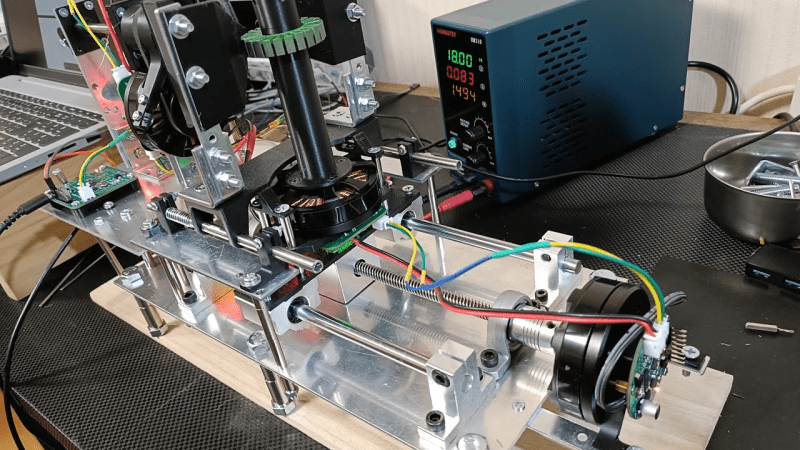
The system is controlled by an STM32G431 microcontroller. The motor driver used is the DRV8313. There are three GBM5208 75T Gimbal motors for close-loop angle control, and one BE4108 60T Gimbal motor for torque control. The torque control motor was built with this machine! [Yuchi] says that the Gimbal motors used are designed to be smooth, precise, and powerful at low speeds.
The components of the machine communicate with each other over a CAN bus. This simplifies wiring as components (such as motor controller boards) only require four connections.
Thanks to [Ben] for writing in to let us know about this project. If you’re interested in automated wire winding we have certainly covered that before here at Hackaday. You might like to check out Tips For Winding Durable Coils With Nice, Flat Sides or Coil Winding Machine Makes It Easy.


Why fixate on STM32 when literally the same task can be acomplished by any MCU made in the last 40 years. You could even build this using NES or Amiga.
My spidey senses tell me it’s mostly marketing BS (or riding the hype.)
Why change if something works for the maker? Using any other microcontroller for the sake of not using a STM32 is counter-productive, specially on the hobby field. And even if their goal is to sell kits, if they are already know how to productively use a STM32 there’s literally no reason to use another microcontroller, just the time they would spend to learn the intricacies of another architecture would be better spent developing the system. The only reason to change would be if the other microcontroller offers some useful feature for the project that a STM32 does not have or is difficult to implement.
My first guess is that it is much easier and more reproducible to source an STM32 than an NES or Amiga in most regions at this time
“which microcontroller did you use” would be among the first questions the person would get asked on the internet, along with “which motors” and “what software” and they happened to point out all three in advance
you really need to ease off the cynicism. It’s at the point where you make yourself unhappy for no reason whatsoever
Coulda done it with a 555
🤣
Fixate? You look that up first?
Because it has multiple hardware timers so you can choose 3 which can then be cascaded with a phase difference and output PWM. It was literally designed to drive 3 phase BLDC motors
Why would you use an inferior software solution when a hardware solution exists (with a very fast ARM Cortex MCU too!)
hmm, 3phase brushless dc motors? that sounds to me like the ultimate oxymoron, but there again I tend to regard brushless dc motors as an oxymoron, as they are driven by ac current anyway. they’re no more dc motors than any ac motor driven by an inverter.
Brianac
You could theoretically build anything with any turing-complete device, what’s your point?
Mentioning the micro is no different than mentioning the other parts by number, it’s weird you’d fixate on that detail especially on a website like this.
Might be sponsored, might not be, it could be the person knows the chips inside out, has a pile of them, can get them easily, any number of reasons including the Youtube algorithm, search tags etc.
Personally? I know it could be accomplished with lots of different microcontrollers or even full on computers, but I’m more interested in the machine itself
Probably because ST has an inexpensive eval board that makes it easy to prototype. B-G431B-ESC1 is $19 on Digikey.
fixate? He just mentions the MCU he used. I can ask you the same. Why do you “fixate” on NES or Amiga?
NES and Amiga are not MCUs and you cannot put them on a custom board. I’m sure there are 8-bit MCUs that have the same peripherals as the STM32 he chose. But STM32’s are affordable and are available in budget versions and high-end version. Also many development boards and examples are available.
hehe quite a comment, and my reply is barely different than the others…but i just wanted to throw out, i switched from stm32 to pico rp2040 because at the single-digit-dollars price point, the rp2040 is just plain easier to program. it’s just easier to plug a usb cable to and upload your software to it. at that price in stm32 world, i would have to get a ‘blue pill’ sort of board (counterfeit?) and then solder on a new resistor to fix the defective one, and then i’d still need to use a separate board to program it.
but if i had a big pile of stm32s and a good established pipeline for programming them, i would still use them. i liked the stm32. most of the arm microcontrollers are pretty good and have a pretty good range of i/o peripherals too. i’m sure esp32 is good too
Really impressive build. I always wondered how they wound motors. Now I kinda do.
If you’re going to go through all that effort to make something “better” than a commercial motor, it would be a great opportunity to switch to something better than round copper wire for windings: You could use silver in a rectangular cross section for lower resistance and better packing fraction, for 16% better conductivity. Or use aluminum, for a double the conductivity per unit mass. Or Litz wire for higher conductivity at high frequency operation. Or tubing for water cooled conductors.
Manufacturing custom wire is quite a step above winding a pre-made stator
But it’s not custom wire. Not readily available at your local hardware store, but commercial versions of everything I mentioned exist. I have used them all, and more (like zero-permeability aluminum-copper alloy wire, which is neat stuff)
man, i’m not gonna say those are not neat innovations but each one requires quite a bit of specialization in your winding machine. tackle one problem at a time, i say.
https://newatlas.com/technology/kist-cnt-cscec-carbon-nanotube-wire/
Try this wire? 🤔
Well, it works, and that”s great. However, the motors seem to lack the fine control that is needed to turn this into a really great machine. FOC is quite good at improving motor efficiency for high rpm applications (such as driving wheels or propellers), but it’s not very good for precise positioning. There is not much info about the motor drivers used algorithms and what sort of feedback is used. Using stepper motors is a more “traditional” approach for driving the axis of a CNC machine, as the higher pole pair count increases stiffness and low rpm positioning accuracy. But high positoning accuracies can surely be achieved with a BLDC motor. There is very little difference between “BDLC” and “PMSM”, and PMSM servomotors (with 8 or so pole (pairs?) are commonly available with 17-bit resolution encoders and these are generally seen as quite a step up from the generic stepper motors.
The motors used here have a 350Kv rating, i.e. with a 20V power supply they would run at 7000rpm. For the positioning axis, which run at a very low RPM only a very small portion of the motors capabilities are used. In addition to better software (and feedback) adding a (belt) gear reduction is another way to improve it. First, you improve the positioning resolution inherently with the gear ratio, and second, because the motor needs less torque to deliver the same torque at the positioning shaft, the drive circuit is “stiffer”, which further improves positioning accuracy.
“Using stepper motors is a more “traditional” approach for driving the axis of a CNC machine, as the higher pole pair count increases stiffness and low rpm positioning accuracy”
Strange, My Haas vf3 uses servo motors. My fadal 3016 uses servo motors. Every DMG Mori, Mazak, and Okuma mill Ive ever worked with used servo motors. The only CNCs Ive ever seen with stepper motors are tiny table top hobbyist toys.
No, not strange at all. I also wrote about those motors, and the divers need to be tuned just right to make it all work properly. The motors in the coil winder presented here are clearly not tuned right, or they lack the high resolution feedback to enable the precise control, or some combination (or other…).
Steppers are only traditional on hobby machines, all the serious stuff has used servos since forever.
Maybe it was better if I added the “hobby” remark, but for the rest, it depends on what you define as “serious stuff”. Sure, those industrial servo’s have more performance then stepper motors, but big stepper motors are used quite often in the lower tier of machines. They are for example very common in the big flatbed routers (wood, stone, “advertisement”) and those things easily have a work envelope of 4 square meters and more. I would call that quite serious.
A very long time at school (mid ’90-ies) we had a converted bridgeport at school for CNC lessons. It had quite big Nema 42 stepper motors.
Loosely defined ‘servo motor’ though.
None of the machines mentioned use a pot of position sensing, that would suck.
Even old machines w DC motors have tachometers and pulse counters for position control.
“Loosely defined ‘servo motor’ though. None of the machines mentioned use a pot of position sensing, that would suck.”
Loose indeed.
Hobby servos use potentiometers for position control. Fine for applications constrained below 360 degrees of rotation. Crap beyond those limited applications.
Tachometers dont provide position information beyond an expected position relative to start.
Pulse Counters generally lack directional indication so they also only provide expected relative position. They also get lost if power is interrupted, requiring rehoming.
Most industrial servo motors use quadrature encoders. They provide both speed and position feedback, making them ideal for closed-loop control systems.
I think one of the points of the project was to do it cheaply and I can absolutely get on side with that, the servomotors I have were the wrong side of $1200 each and the gear to control them was not cheap either.
pshaw! PSHAW, i say.
BLDC is a stepper motor, just with relatively large steps. the reason people love the traditional stepper motors is that you can often get away with open loop control on them. so long as you don’t need too much precision from ‘micro-stepping’, you can simply tell it to step N times and you know how many revolutions that is.
but this is closed loop!!!!!! !!!
closed loop is superior and if they worked through their problems then they worked through their problems.
everyone else here is saying ‘servo’, and i’m really just spelling out that servo is a synonym for closed loop.
want to take back the ‘DC’ in my comment :)
Double Phsaw!! to you too. I once had a disagreement with someone on EEVblog who was convinced a BLDC motor was “significantly different” from a PMSM motor. Best I know, the BLDC has a bit of a trapezoidal voltage characteristic and is more optimized for power delivery, and the PMSM is more “classical” sinusoidal. I won’t be surprised if the “BLDC” turns out to be the better choice for nearly every application. Instead of the Sine / Cosine (cordic?) calculations, you can put linear interpolation in the motor controller to ease the math, maybe some correction factor or a LUT. But higher efficiency sort of translates into higher power density.
And it’s OK to leave in the DC in a BLDC motor. They are called DC because they have a similar motor characteristic as brushed DC motors, but the commutaton is done electronically.
I would be curious about using an AC induction motor for accurate position control. That would mean calculating and applying a continuous rotating field to get a static torque with no movement, but I’m sure it can be done. But power to weight of induction motors is not very high, and the cost of decent quality (3 phase) motors is also not very low so there does not seem much reason to go this way.
Clever build I like what you’ve done here. What can be used other than iron for winding on? Carbon fiber? Just wondering.
I don’t know buy there’s a open source project for carbon fiber winding.
https://www.youtube.com/watch?v=7cabr47hHPI&t=11s
awesome! I’d love to build it
Very nice work…
What we have not yet seen is how it handles the transition from winding one coil on one tooth of the stator to the next coil, and any directional reversing necessary therein. I’d be interested to see that part too. I guess manual intevention would be required when it comes time to finish off the first phase and run the next phase and then the third phase’s wires, but so long as this machine can wind all coils within a single phase in one go then it is a superb labour saving device.
Also, Hackaday headline writers…it is not a “brushless DC motor” winding machine, but just a “brushless motor” winding machine. Whether you call a motor brushless DC or brushless AC, or some other name, really depends on exactly what sort of driving circuitry and control software it is connected to when it is running.
P.S. I’m guessing he used BLDC motors under FOC control as his “servos” in this, rather than using steppers simply because the BLDC’s are lighter weight, which wouldn’t matter for the fixed motor driving the leadscrew but makes things easier for the motor which rides along the leadscrew so as to turn stators about their axis.