Eric Strebel peeks through his Pfaff 463 industrial sewing machine.

Simple Upgrades Make An Old Industrial Sewing Machine New Again

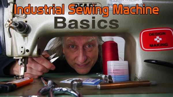
Well, this is a pleasant surprise: it seems that industrial designer [Eric Strebel] recently got a hold of an industrial sewing machine to tackle the softer side of prototyping. What doesn’t surprise us is that he did some upgrades to make it more user-friendly. Check them out in the video embedded below.

So, what’s the difference between a machine like this and what you might have around the house? Domestic sewing machines have a motor about the size of your fist, and it’s inside the machine’s body. Modern domestics can do light-duty work, but they can’t handle making bags and upholstery or sewing a bunch of layers of any material together. Industrial machines have either clutch or servo motors that are easily five times the size of a domestic’s motor, and are built into the table along with the machine.

Pfaff 463 industrial sewing machine with its new brushless DC servo motor.
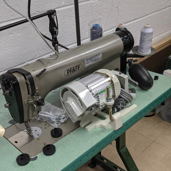
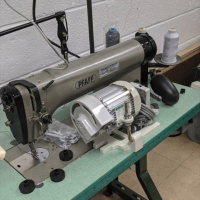
[Eric] found this Pfaff 463 on Craigslist. It was built somewhere around 1950, and it only does one thing — a single-needle, straight stitch, forward or reverse — but it will do it through damn near anything you want (unlike those computerized hunks of plastic made for home use nowadays). Again, these machines are always built into a table, and they come with a lamp.  While the machine itself may be a workhorse, the light is wimpy, so [Eric] replaced it with a goose-neck LED light that has a magnet for sticking it anywhere light is required around the machine.

No matter the size, electric sewing machines are driven with a foot pedal. On a domestic, the pedal is loose and you just put it on the floor wherever you want, but industrial foot pedals are built into the table frame. [Eric] drilled a bunch of new holes in the side of the pedal so he can move the connecting rod closer to the pivot point. This gives him better control with less footwork.

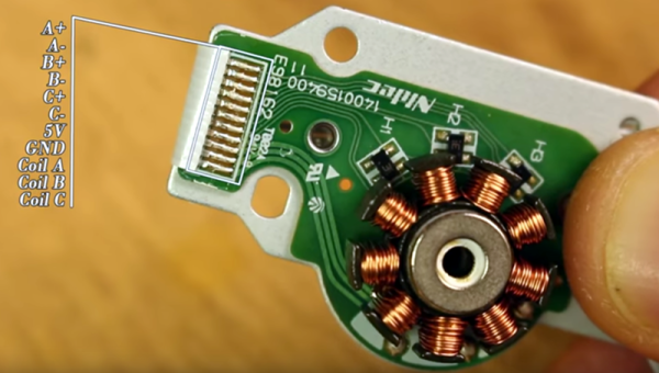
The biggest, baddest upgrade [Eric] did was to the motor. Although there was nothing wrong with the original  clutch motor, it makes the machine go very fast so that garment workers can fulfill their quotas. Because of this, it’s difficult to control. He upgraded to a brushless DC servo motor for greater precision and easier prototyping. He got really lucky, too, because it mounted directly into the old holes.

We agree wholeheartedly with [Eric]’s sentiment about old sewing machines, or any old machine for that matter. They tend to be overbuilt because planned obsolescence wasn’t a thing yet. If you can’t afford or find an industrial, an old Singer or something similar will likely serve your purpose, as long as you use the right needle.

If you already have an old domestic machine sitting around, you might be able to breathe new life into it with a 3D printer.

Continue reading “Simple Upgrades Make An Old Industrial Sewing Machine New Again”

Visualise ESC Problems With LEDs

For many in the RC community, blowing up an Electronic Speed Controller (ESC) means one thing: throwing it away and buying another one. However, if you’re regularly pushing the limits or simply hate waste, fixing failed units is an option. To assist in this task, [LouD] built an ingeniously simple ESC tester.

The board is designed to be wired in parallel with a brushless DC motor when hooked up to an ESC. The board packs two LEDs per phase, wired in opposite directions. Thus, current flow in both directions can be visualised on a phase-by-phase basis. If everything is operational, the red and green LEDs on each phase should glow evenly as the throttle is ramped up. However, if there are problems, it will be readily apparent as the blinking becomes erratic or one or more LEDs fails to light at all.

It’s a nifty little device that would prove useful when testing  a pile of possibly-defective units. It’s also a quick way to verify a fix. The project is up on OSHPark should you wish to order your own.

Continue reading “Visualise ESC Problems With LEDs”

The Current Advances Of PCB Motors

There’s something to be said about the falling costs of printed circuit boards over the last decade. It’s opened up the world of PCB art, yes, but it’s also allowed for some experimentation with laying down fine copper wires inside a laminate of fiberglass and epoxy. We can design our own capacitive touch sensors. If you’re really clever, you can put coils inside four-layer PCBs. If you’re exceptionally clever, you can add a few magnets and build a brushless motor out of a PCB.

We first saw [Carl]’s PCB motor at the beginning of the year, but since then we’ve started the Hackaday Prize, [Carl] entered this project in the Prize, and this project already made it to the final round. It’s really that awesome. Since the last update, [Carl] has been working on improving the efficiency and cost of this tiny PCB motor. Part of this comes from new magnets. Instead of a quartet of round magnets, [Carl] found some magnets that divide the rotor into four equal pieces. This gives the rotor a more uniform magnetic field across its entire area, and hopefully more power.

The first version of this 3D printed PCB motor used press-fit bushings and a metallic shaft. While this worked, an extra piece of metal will just drive up the cost of the completed motor. [Carl] has redesigned the shaft of the rotor to get rid of the metallic axle and replace it with a cleverly designed, 3D printed axle. That’s some very nice 3D printing going on here, and something that will make this motor very, very cheap.

Right now, [Carl] has a motor that can be made at any board house that can do four-layer PCBs, and he’s got a rotor that can be easily made with injection molding. The next step is closed-loop control of this motor. This is a challenge because the back-EMF generated by four layers of windings is a little weak. This could also be accomplished with a hall sensor, but for now, [Carl] has a working PCB motor. There’s really only one thing to do now — get the power output up so we can have real quadcopter badges without mucking around with tiny brushed motors.

[Carl] has put up a few videos describing how his PCB motor works; you can check those out below.
Continue reading “The Current Advances Of PCB Motors”

Completely Scratch-Built Electronic Speed Controller

Driving a brushless motor requires a particular sequence. For the best result, you need to close the loop so your circuit can apply the right sequence at the right time. You can figure out the timing using a somewhat complex circuit and monitoring the electrical behavior of the motor coils. Or you can use sensors to detect the motor’s position. Many motors have the sensors built in and [Electronoobs] shows how to drive one of these motors in a recent video that you can watch below. If you want to know about using the motor’s coils as sensors, he did a video on that topic, earlier.

The motor in question was pulled from an optical drive and has three hall effect sensors onboard. Having these sensors simplifies the drive electronics considerably.

Continue reading “Completely Scratch-Built Electronic Speed Controller”

IQ Makes Smarter Motors

We think of motors typically as pretty dumb devices. Depending on the kind, you send them some current or some pulses, and they turn. No problem. Even an RC servo, which has some smarts on board, doesn’t have a lot of capability. However, there is a new generation of smart motors out that combine the mechanical motor mechanism with a built-in controller. [Bunnie] looks at one that isn’t even called a motor. It is the IQ position module.

Despite the name, these devices are just a brushless DC motor (BLDC) with a controller and an API. There’s no gearing, so backdriving the motor is permissible and it can even double as a motion sensor. The video below shows [Bunnie] making one module track the other using just a little bit of code.

Continue reading “IQ Makes Smarter Motors”

This Tiny Motor Is Built Into A PCB

Mounting a motor on a PCB is nothing new, right? But how about making the PCB itself part of the motor? That’s what [Carl Bugeja] has done with his brushless DC motor in a PCB project, and we think it’s pretty cool.

Details on [Carl]’s Hackaday.io page are a bit sparse at this point, but we’ve been in contact with him and he filled us in a little. The PCB contains the stator of the BLDC and acts as a mechanical support for the rotor’s bearing. There are six spiral coils etched into the PCB, each with about 40 turns. The coils are distributed around the axis; connected in a wye configuration, they drive a 3D-printed rotor that has four magnets pressed into it. You can see a brief test in the video below; it seems to suffer from a little axial wobble due to the single bearing, but that could be handled with a hat board supporting an upper bearing.

We see a lot of potential in this design. [Carl] mentions that the lack of cores in the coil limit it to low-torque applications, but it seems feasible to bore out the center of the coils and press-fit a ferrite slug. Adding SMD Hall sensors to the board for feedback would be feasible, too — in fact, an entire ESC and motor on one PCB could be possible as well. [Carl] has promised to keep the project page updated, and we’re looking forward to more on this one.

For a more traditional approach to printed motors, check out this giant 3D-printed BLDC.

Continue reading “This Tiny Motor Is Built Into A PCB”

Fidget Spinner Becomes A Brushless Motor; Remains Useless

Your grandmother means well. But by the time she figures out something’s a fad, it is old news. So maybe you got a fidget spinner in your stocking this year. Beats coal. Before you regift it to your niece, you could repurpose it to be a motor. Technically, [B.Aswinth Raj] made a brushless motor, although it isn’t going to fly your quadcopter anytime soon, it is still a nice demonstrator.

You can see a video below. The idea is to put magnets on the spinner and use an electromagnet to impart energy into the spinner which is on a piece of threaded rod left over from your last 3D printer build. A hall effect sensor determines when to energize the electromagnet.

A brushed motor uses a spring-loaded brush to carry current through to the motor’s coils and keep the magnetic field oriented properly. A brushless motor works differently. There are several schemes that will work, but the one [Raj] uses is the most common. He adds fixed magnets on the rotor then uses an electromagnet to provide the correct push at the right time. A practical brushless motor will likely have more than one coil, though, and the controller has to do a particular sequence to move the rotor around the rotation.

If you want to see the insides of a real motor, we looked at how to rewind them earlier. If you’d rather repurpose your spinner to something more practical, you could always make some music.

Continue reading “Fidget Spinner Becomes A Brushless Motor; Remains Useless”