When we do textbook analysis, we tend to ignore the real-world concerns for the sake of learning. So, a typical theoretical voltage divider is simply two resistors. But if you examine a low-pass RC filter, you’ll see a single resistor and a capacitor. What if you combine them? That’s what [Old Hack EE] did in a recent video, and you can check it out below.
It helps if you are familiar with Thevenin equivalents and, of course, Ohm’s Law. There’s also a bit of algebra, but nothing too complicated. The example design has a lossy filter at 100 Hz.
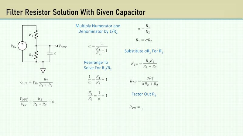
Of course, RC filters are easy to understand if you think of them as voltage dividers with a frequency-variable resistance, which is what the math is basically saying. The load impedance, in this case, is R2 in parallel with Xc at a given frequency.
He mentions that you might find a circuit like this in a power supply. However, it is also common to see this circuit wherever a divider drives a load with capacitance or even parasitic capacitance in cables or circuit boards.
We’ve discussed Thevenin equivalence modeling before. If you want really good filters, you are probably going to need op-amps.


Thevenin and Norton equivalents would of course be included in the basic textbook analysis if you read the textbook a little further. The challenge here is that people aren’t reading the textbook, but some second hand “tutorial” which only includes the two resistor voltage divider and the RC filter as separate cases.
It is actually quite simple – at DC, the capacitor can be ignored and it’s simply a voltage divider of R2/(R1+R2). The frequency response is that of a first order RC with R1 in parallel with R2, so a time constant of (R1||R2)*C.
This is not a trick or a hack, but basic electronics.
The downside of this is that it might load the signal too much or it might have a too high output impedance for an ADC input. If that is a problem tweak the values or use an active filter.