
Human existence boils down to one brutal fact: however much food you have, it’s enough to last for the rest of your life. Finding your next meal has always been the central organizing fact of life, and whether that meal came from an unfortunate gazelle or the local supermarket is irrelevant. The clock starts ticking once you finish a meal, and if you can’t find the next one in time, you’ve got trouble.
Working around this problem is basically why humans invented agriculture. As tasty as they may be, gazelles don’t scale well to large populations, but it’s relatively easy to grow a lot of plants that are just as tasty and don’t try to run away when you go to cut them down. The problem is that growing a lot of plants requires a lot of water, often more than Mother Nature provides in the form of rain. And that’s where artificial irrigation comes into the picture.
We’ve been watering our crops with water diverted from rivers, lakes, and wells for almost as long as we’ve been doing agriculture, but it’s only within the last 100 years or so that we’ve reached a scale where massive pieces of infrastructure are needed to get the job done. Above-ground irrigation is a big business, both in terms of the investment farmers have to make in the equipment and the scale of the fields it turns from dry, dusty patches of dirt into verdant crops that feed the world. Here’s a look at the engineering behind some of the more prevalent methods of above-ground irrigation here in North America.
Crop Circles
Center-pivot irrigation machines are probably the most recognizable irrigation methods, both for their sheer size — center-pivot booms can be a half-mile long or more — and for the distinctive circular and semi-circular crop patterns they result in. Center-pivot irrigation has been around for a long time, and while it represents a significant capital cost for the farmer, both in terms of the above-ground machinery and the subsurface water supply infrastructure that needs to be installed, the return on investment time can be as low as five years, depending on the crop.

Effective use of pivot irrigation starts with establishing a water supply to the pivot location. Generally, this will be at the center of a field, allowing the boom to trace out a circular path. However, semi-circular layouts with the water supply near the edge of the field or even in one corner of a square field are also common. The source must also be able to supply a sufficient amount of water; depending on the emitter heads selected, the boom can flow approximately 1,000 gallons per minute.
The pivot tower is next. It’s generally built on a sturdy concrete pad, although there are towable pivot machines where the center tower is on wheels. The tower needs to stand tall enough that the rotating boom clears the crop when it’s at its full height, which can be substantial for crops like corn. Like almost all parts of the machine, the tower is constructed of galvanized steel to resist corrosion and to provide a bit of anodic protection to the underlying metal.
The tower is positioned over a riser pipe that connects to the water supply and is topped by a swivel fitting to change the water flow from vertical to horizontal and to let the entire boom rotate around the tower. For electrically driven booms, a slip ring will also be used to transfer power and control signals from the fixed control panel on the tower along the length of the boom. The slip ring connector is located in a weather-tight enclosure mounted above the exact center of the riser pipe.
The irrigation boom is formed from individual sections of pipe, called spans. In the United States, each span is about 180 feet long, a figure that makes it easy to build a system that will fit within the Public Land Survey System (PLSS), a grid-based survey system based on even divisions called sections, one mile on a side and 640 acres in area. These are divided down into half-, quarter-, and finally quarter-quarter sections, which are a quarter mile on a side and cover 40 acres. A boom built from seven spans will be about 1,260 feet long and will be able to irrigate a 160-acre quarter-section, which is a half-mile on a side.
The pipe for each span is usually made from galvanized steel, but aluminum is also sometimes used. Because of the flow rates, large-diameter pipe is used, and it needs to be supported lest it sag when filled. To do this, the pipe is put into tension with a pair of truss rods that run the length of the span, connecting firmly to each end. The truss rods and the pipe are connected by a series of triangular trusses attached between the bottom of the pipe and the truss rods, bending the pipe into a gentle arch. The outer end of each span is attached to a wheeled tower, sized to support the pipe at the same height as the center tower. The boom is constructed by connecting spans to each other and to the center pivot using flexible elastomeric couplings, which allow each span some flexibility to adjust for the terrain of the field. Sprinkler heads (drops) are attached to the span by elbows that exit at the top of the pipe. These act as siphon breakers, preventing water from flowing out of the sprinkler heads once water flow in the boom stops.
Different sprinkler heads are typically used along the length of the boom, with lower flow rate heads used near the center pivot. Sprinkler heads are also often spaced further apart close to the pivot. Both of these limit the amount of water delivered to the field where the boom’s rotational speed is lower, to prevent crops at the center of the field from getting overwatered. Most booms also have an end gun, which is similar to the impulse sprinklers commonly used for lawn irrigation, but much bigger. The end gun can add another 100′ or more of coverage to the pivot, without the expense of another length of pipe. End guns are often used to extend coverage into the corners of square fields, to make better use of space that otherwise would go fallow. In this case, an electrically driven booster pump can be used to drive the end gun, but only when the controller senses that the boom is within those zones.

Most center-pivot machines are electrically driven, with a single motor mounted on each span’s tower. The motor drives both wheels through a gearbox and driveshaft. In electrically driven booms, only the outermost span rotates continuously. The motors on the inboard spans are kept in sync through a position-sensing switch that’s connected to the next-furthest-out span through mechanical linkages. When the outboard span advances, it eventually trips a microswitch that tells the motor on the inboard span to turn on. Once that span catches up to the outboard span, the motor turns off. The result is a ripple of movement that propagates along the boom in a wave.
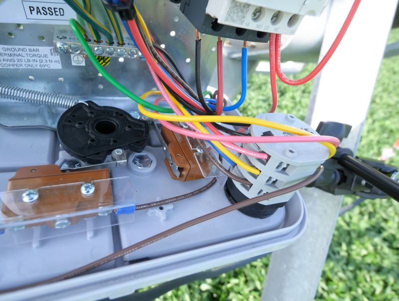
While electrically driven center-pivot machines are popular, they do have significant disadvantages. Enterprising thieves often target them for copper theft; half a mile of heavy-gauge, multi-conductor cable sitting unattended in a field that could take hours for someone to happen upon is a tempting target indeed. To combat this, some manufacturers use hydrostatic drives, with hydraulic motors on each wheel and a powerful electric- or diesel-driven hydraulic pump at the pivot. Each tower’s wheels are controlled by a proportioning valve connected to the previous span via linkages, to run the motors faster when the span is lagging behind the next furthest-out tower.
Aside from theft deterrence, hydrostatic-drive pivots tend to be mechanically simpler and safer to work on, although it’s arguable that the shock hazard from the 480 VAC needed for the motors on electrically driven pivots is any less dangerous than hydraulic injection injuries from leaks. Speaking of leaks, hydrostatic pivots also pose an environmental hazard that electric rigs don’t; a hydraulic leak could potentially contaminate an entire field. To mitigate that risk, hydrostatic pivots generally use a non-toxic hydraulic fluid specifically engineered for pivots.
Occasionally, you’ll see center-pivot booms in fields that aren’t circular. Some rectangular fields can be irrigated with pivot-style booms that are set up with drive wheels at both ends. These booms travel up and down the length of a field with all motors running at the same speed. Generally, water is supplied via a suction hose dipping down from one end of the boom into an irrigation ditch or canal running alongside the field. At the end of the field, the boom reverses and heads back down the way it came. Alternatively, the boom can pivot 180 degrees at the end of the field and head back to the other end, tracing out a racetrack pattern. There are also towers where the wheels can swivel rather than being fixed perpendicularly to the boom; this setup allows individual spans or small groups to steer independently of the main boom, accommodating odd-shaped fields.

Rolling, Rolling, Rolling
While center-pivot machines are probably the ultimate in above-ground irrigation, they’re not perfect for every situation. They’re highly automated, but at great up-front cost, and even with special tricks, it’s still not possible to “square the circle” and make use of every bit of a rectangular field. For those fields, a lower-cost method like wheel line irrigation might be used. In this setup, lengths of pipe are connected to large spoked wheels about six feet in diameter. The pipe passes through the center of the wheel, acting as an axle. Spans of pipe are connected end-to-end on either side of a wheeled drive unit, forming a line the width of the field, up to a quarter-mile long, with the drive unit at the center of the line.
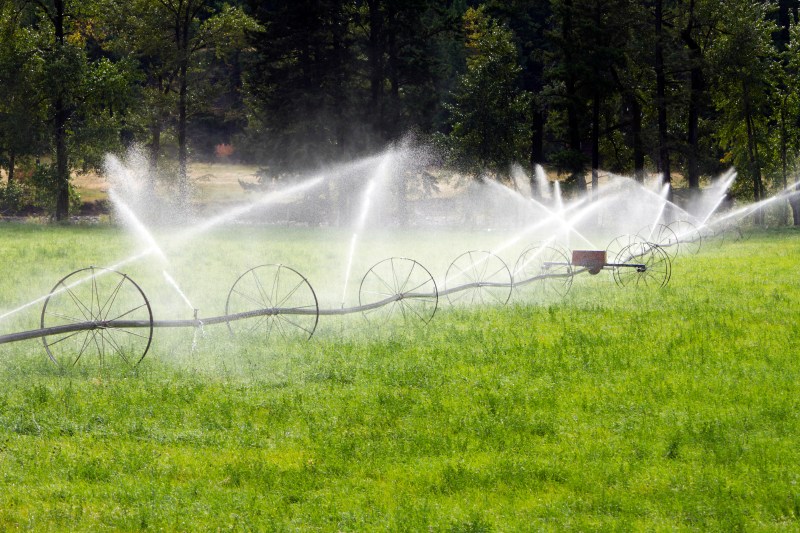
In use, the wheel line is rolled out into the field about 25 feet from the edge. When the line is in position, one end is connected to a lateral line installed along the edge of the field, which typically has fittings every 50 feet or so, or however far the sprinkler heads that are attached at regular intervals to the pipe cover. The sprinklers are usually impulse-type and attached to the pipe by weighted swivel fittings, so they always remain vertical no matter where the line stops in its rotation. The heads were traditionally made of brass or bronze for long wear and corrosion resistance, but thieves attracted to them for their scrap value have made plastic heads more common.
Despite their appearance, wheel lines do not continually move across the field. They need to be moved manually, often several times a day, by running the drive unit at the center of the line. This is generally powered by a small gasoline engine which rotates the pipe attached to either side, rolling the entire string across the field as a unit. Disconnecting the water, rolling the line, and reconnecting the line to the supply is quite labor-intensive, so it tends to be used only where labor is cheap.
Reeling In The Years
A method of irrigation that lives somewhere between the labor-intensive wheel line and the hands-off center-pivot is hose reel irrigation. It’s more commonly used for crop irrigation in Europe, but it does make an occasional appearance in US agriculture, particularly in fields where intensive watering all season long isn’t necessary.
As the name suggests, hose reel irrigation uses a large reel of flexible polyethylene pipe, many hundreds of feet in length. The reel is towed into the field, typically positioned in the center or at its edge. Large spades on the base of the reel are lowered into the ground to firmly anchor the reel before it’s connected to the water supply via hoses or pipes. The free end of the hose reel is connected to a tower-mounted gun, which is typically a high-flow impulse sprinkler. The gun tower is either wheeled or on skids, and a tractor is used to drag it out into the field away from the reel. Care is taken to keep the hose between rows to prevent damage to the crops.
Once the water is turned on, water travels down the hose and blasts out of the gun tower, covering a circle or semi-circle a hundred feet or more in diameter. The water pressure also turns a turbine inside the hose reel, which drives a gearbox that slowly winds the hose back onto the reel through a chain and sprocket drive. As the hose retracts, it pulls the gun back to the center of the field, evenly irrigating a large rectangular swath of the field. Depending on how the reel is set up, it can take a day or more for the gun to return to the reel, where an automatic shutoff valve shuts off the flow of water. The setup is usually moved to another point further down the field and the process is repeated until the whole field is irrigated.
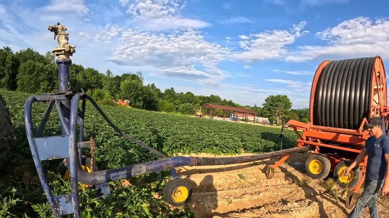
Although hose reels still need tending to, they’re nowhere near as labor-intensive as wheel lines. Farmers can generally look in on a reel setup once a day to make sure everything is running smoothly, and can often go several days between repositioning. Hose reels also have the benefit of being much easier to scale up and down than either center-pivot machines or wheel line; there are hose reels that store thousands of feet of large-diameter hose, and ones that are small enough for lawn irrigation that use regular garden hose and small impulse sprinklers.


Correction note; The pipe is put into compression (not tension) by the tension in the pair of truss connected cables below them, causing the pipe to bow upwards and so support itself.
https://youtu.be/7j1lMs7fcIQ?si=4D42HvSM3iZgAhBt for some live-action center-pivot education
Why are the crop circles often arranged in a rectangular grid instead kf a more space efficient hexagonal one?
Also, those gaps in between would make excellent ecological improvement areas, e.g. as https://en.m.wikipedia.org/wiki/Wildflower_strip
Because farmers usually own rectangular plots, so the center pivot designs are sized for quarter section plots, and you would need a HUGE chunk of land to put in a bunch of hexagonal close packed units while not losing more on the edges than you gain in the middle.
Around here there are a lot of systems that have a spare span on the end, that folds in and follows the main arm along the areas where the circle is closest to the property line, but in the corners, it swings out to water areas that the gun can’t reach. (And they have guns on them too.)
Because the roads they occupy and property boundaries are almost always in a grid pattern. Even in the case of a very large field it still makes more economical sense to have one or two very large pivots than multiple smaller units.
Yes, you give up some irrigated acreage, but your installation and maintenance costs are lower and they’re much easier to manage. Things like end-guns or even a “swing arm” boom can help reach further out into the corners and maximize the irrigated acreage for less added cost than another pivot.
Land ownership is on the lines of a square grid, and if you acquire several smaller farms to make a larger one, you’re probably not going to reposition the centers after the fact. That means either running new large-diameter pipes or digging new wells.
Meanwhile, the unirrigated corners do in fact get used for ecological improvement, including food and habitat for pollinators, predators of crop pests, and wild birds.
Or they get used for another crop that’s not so thirsty and can be irrigated by other means. Or they get another, smaller pivot installed.
(For more about all of these, see USDA Natural Resources Conservation Service. 2016. Plant Materials Technical Note 1: What To Do With Irrigation Pivot Corners. West National Technology Support Center, Portland, OR.)
The Oregon legislature also considered a bill this year to promote installation of solar panels in irrigation corners, to compensate farmers who would put another crop in their corners if they could, but are barred from expanding irrigation in order to maintain the aquifers.
My guess is that farmers owning rectangular plots is mostly a red herring. My own best guess is that the land just cost (next to) nothing. The amount of land that can be utilized is probably limited by the availability of water in the area.
I once flew over Spain and you could see groups of those circles, but with a lot of empty and mostly barren land around it.
Not sustainable. Too many people. Not enough fresh water.
You first.
I am on my way out, with DNR orders on file. Your turn.
A person with no children has no reason to invest in the future.
A person who hates humanity has no reason to have children.
It’s a catch-22; why do you care about a world you have no reason to care about when you’re gone?
Be specific. What did he say should be done, that you want him to do first?
Nonsense.
Just repeating derp.
When water gets more expensive, you switch to drip.
Israel has led the way!
Center pivot is more efficient (of water) but more expensive than flood irrigation.
I can’t use it in my garden, but that’s down to crop.
Buds hate sprinklers.
I could use drip, but N cal.
Fresh water is INXS.
So KISS.
‘World needs ditch diggers too.’
I clear out my backyard irrigation ditches once/year.
Oops, looks like it’s time for you to take your meds!
It’s always time to smoke my meds.
Goes best with strong coffee.
Only halfwits don’t realize that fresh water is INXS for most human inhabited land.
Want to pretend S Cal is the norm.
Even there, the LA river flows enough water for them.
They just let it run into the ocean because it’s easier to just vote themselves someone else’s water.
How about we allow the population to decline naturally, so that water never gets more expensive in the first place?
‘Idiocracy’ is a documentary.
Someone design a CNC-like system with proper X and Y axi . . . . .
“…but it’s only within the last 100 years or so that we’ve reached a scale where massive pieces of infrastructure are needed to get the job done.”
I’m going to argue this one. Civilizations throughout history evolved (sometimes massive) infrastructure and often very clever end-point distribution systems. Canals, sloughs, viaducts etc. are still in place from these, and modern systems use very similar things with the improvement of more water-efficient endpoint spray/drip/subsurface irrigation in place of the dam systems, waterwheel lift pumps, windmills, and other clever gadgets of their time.
As far as automation goes, I’m glad that some of these move themselves as having to move long aluminum irrigation pipes around as a summer job wasn’t (and probably isn’t) all that much fun…
I’d argue the whole point of civilization is massive infrastructure to support agriculture.
And the whole point of agriculture was and is beer!
In my youth they used to do pivot corners with wheel line or (God help us all!) hand line. Doubt if any of the big boys would waste labor on hand line nowadays. Labor cost higher than corner yield profit. Anyway, hand line was nothing, labor wise, to row siphon tubes. They required not only labor, but actual skill, nay art. There was also gate line; a vulgar method IMHO. Tis all automation now, if one can afford it. All to the good, too, it was a lot of work to look after just a few acres not so long ago.
love these articles
Yeah, as Squirrely Bob mentioned above, you forgot to mention hand lines. I used to move two versions of those: on whose connections were fastende with a ~8 inch alumnium hook, or others that used a u-profile, spring-assisted rubber seal to lock once water pressure was applied. Both styles were first shut off, then connected to a turned on, flowing opener (read: valve with open connection socket) because you could almost never turn it off and expect the lines to stay connected without water pressure. The openers would be clasped onto riser valves from buiried water lines, and whenever there was a power bump, you would have to run out to check your lines as the aforementioned loss of pressure would result in disconnection and a blowout that could dig a shallow trench in your field in short order.
Also for honorable mention: flood irrigation and gated pipe. Flood irrigaton would have smaller ditches fed by a larger canal and you would have to deploy a plastic tarp secured by a 6-8 ft pole and rocks across the ditch to flood sections of field temporarily, and move them twice daily. I have no insight to gated pipe though; never lived on a place that ran it.
Nobody has mentioned the art on this one yet? I thought it was fantastic.
Ah, OK. now I get it, after going back and looking again. I agree, that is very clever :-)
I used to build and repair these systems. We repped Zimmatic but worked on many brands.
The do have linear move systems which is basically the same structure but the center point becomes a carriage and the last tower as well. It drags a hose or pulls from a ditch and covers a square area.
My introduction to electronics was in the form of my boss at the time showing me a big crate of parts and telling me to “figure out how to make this work”. The contents of the box were parts to create a radio network, GPS positioning equipment for the pivot, RTU’s, controls to up-fit the pivot to be ran from a computer or cell phone and a radio to internet bridge. It took me a couple months but I got it all to work.
But I did it and started a new path in my career and a passion for automation.