The familiar five volts standard from back in the TTL days always struck me as odd. Back when I was just a poor kid trying to cobble together my first circuits from the Forrest Mims Engineer’s Notebook, TTL was always a problem. That narrow 4.75 V to 5.25 V spec for Vcc was hard to hit, thanks to being too poor to buy or build a dedicated 5 V power supply. Yes, I could have wired up four 1.5 V dry cells and used a series diode to drop it down into range, but that was awkward and went through batteries pretty fast once you got past more than a few chips.
As a hobbyist, the five volt TTL standard always seemed a little capricious, but I strongly suspected there had to be a solid reason behind it. To get some insights into the engineering rationale, I did what anyone living in the future would do: I asked ChatGPT. My question was simple: “How did five volts become the standard voltage for TTL logic chips?” And while overall the answers were plausible, like every other time I use the chatbot, they left me wanting more.
Circular Logic
The least satisfying of ChatGPT’s answers all had a tinge of circular reasoning to them: “IBM and other big computer makers adopted 5 V logic in their designs,” and thanks to their market power, everyone else fell in line with the five volt standard. ChatGPT also blamed “The Cascade Effect” of Texas Instruments’ standardization of five volts for their TTL chips in 1964, which “set the tone for decades” and forced designers to expect chips and power supplies to provide five volt rails. ChatGPT also cited “Compatibility with Existing Power Supplies” as a driver, and that regulated five volt supplies were common in computers and military electronics in the 1960s. It also cited the development of the 7805 linear regulator in the late 1960s as a driver.
All of this seems like nonsense, the equivalent of saying, “Five volts became the standard because the standard was five volts.” What I was after was an engineering reason for five volts, and luckily, an intriguing clue was buried in ChatGPT’s responses along with the drivel: the characteristics of BJT transistors, and the tradeoffs between power dissipation and speed.
The TTL family has been around for a surprisingly long time. Invented in 1961, TTL integrated circuits have been used commercially since 1963, with the popular 7400-series of logic chips being introduced in 1964. All this development occurred long before MOS technology, with its wider supply range, came into broad commercial use, so TTL — as well as all the precursor logic families, like diode-transistor logic (DTL) and resistor-transistor logic (RTL) — used BJTs in all their circuits. Logic circuits need to distinguish between a logical 1 and a logical 0, and using BJTs with a typical base-emitter voltage drop of 0.7 V or so meant that the supply voltage couldn’t be too low, with a five volt supply giving enough space between the high and low levels without being too susceptible to noise.
But, being able to tell your 1s and 0s apart really only sets a minimum for TTL’s supply rail. Why couldn’t it have been higher? It could have, and a higher Vcc, like the 10 V to 15 V used in emitter-coupled logic (ECL), might have improved the margins between logic levels and improved noise immunity. But higher voltage means more power, and power means heat, and heat is generally frowned upon in designs. So five volts must have seemed like a good compromise — enough wiggle room between logic levels, good noise immunity, but not too much power wasted.
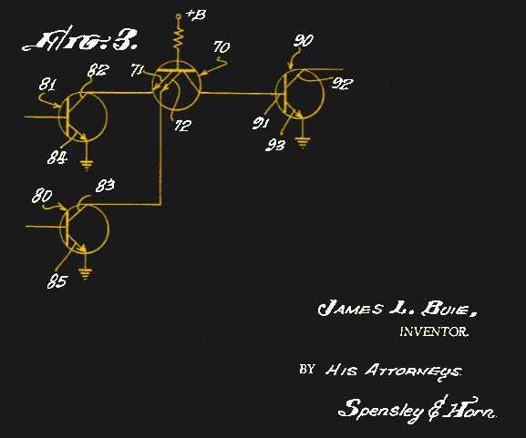
I thought perhaps the original patent for TTL would shed some light on the rationale for five volts, but like most inventors, James Buie left things as broad and non-specific as possible in the patent. He refers only to “B+” and “B-” in the schematics and narrative, although he does calculate that the minimum for B+ would be 2.2 V. Later on, he states that “the absolute value of the supply voltage need be greater than the turn-on voltage of the coupling transistor and that of the output transistor,” and in the specific claims section, he refers to “a source of EMF” without specifying a magnitude. As far as I can see, nowhere in the patent does the five volt spec crop up.
Your Turn
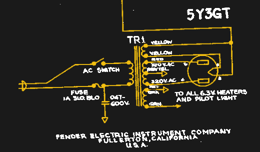
If I were to hazard a guess, the five volt spec might be a bit of a leftover from the tube era. A very common value for the heater circuit in vacuum tubes was 6.3 V, itself a somewhat odd figure that probably stems from the days when automobiles used 6 V electrical systems, which were really 6.3 V thanks to using three series-connected lead-acid cells with a nominal cell voltage of 2.1 V each.
Perhaps the early TTL pioneers looked at the supply rail as a bit like the heater circuit, but nudged it down to 5 V when 6.3 V proved a little too hot. There were also some popular tubes with heaters rated at five volts, such as the rectifier tubes found in guitar amplifiers like the classic Fender “Champ” and others. The cathodes on these tubes were often directly connected to a dedicated 5 V winding on the power transformer; granted, that was 5 V AC, but perhaps it served as a design cue once TTL came around.
This is, of course, all conjecture. I have no idea what was on the minds of TTL’s designers; I’m just throwing out a couple of ideas to stir discussion. But what about you? Where do you think the five volt TTL standard came from? Was it arrived at through a stringent engineering process designed to optimize performance? Or was it a leftover from an earlier era that just happened to be a good compromise? Was James Buie an electric guitarist with a thing for Fender? Or was it something else entirely? We’d love to hear your opinions, especially if you’ve got any inside information. Sound off in the comments section below.


Real tired of hearing about “ChatGPT”.
Having grown up (literally) watching RTL, DTL, AND TTL followed by all the rest; 5 volts was a compromise. High enough to get the speed (10-50 MHz or better), power dissipation (no heatsinks needed), technology (transistors reliability with a >20 year lifetime). Interestingly, the 4000 series CMOS family allowed up to 15 volt operation which was quite useful and popular after 5 volts was set as the TTL standard.
This isn’t a mystery. The choice of 5v was a function of achieving the necessary performance within constraints of the bipolar transistors used at the time.
Some of this stuff was done based on “we screwed around with some of the parameters and that’s what we got” For all we know, it might have started out as “it’s going to be somewhere between 4 and 7 volts” and five eas what the early process worked best at and then from then on you’d be stuck with that for compatibilities sake.
https://www.eevblog.com/forum/chat/so-why-ttl-logic-uses-5v-again/
http://www.eevblog.com/forum/chat/how-are-%27standard%27-voltages-determined/msg184024/
By searching for the right keyword I got answer faster than your LLM hallucinated its hallucinations.
Your second link should be https://www.eevblog.com/forum/chat/how-are-_standard_-voltages-determined/
probably with less energy impact as well
Surprise, people consume energy
Ah, the old boomerforums… A far better source of knowledge than the enshiternet which followed them
I think we should just call it the slopnet.
You need to ask focused questions. If you ask it for the engineering reason, it comes up with the right answer with no drivel.
Thank you for that link.
Let me summarize it:
-It is the lowest voltage that you can use to interface between transistors and vacuum tubes
-Base-emitter junctions of a transistor that are reverse polarized cannot have much more than 6 volts. They start ‘leaking’ and accumulate time based damage.
-first logic chips were bipolar and had quite a bit a static current consumption resulting in heat. higher voltage means more heat…
-early chip technology used for digital suffered from scaling problems. they needed quite a bit of distance to ‘hold’ a standoff voltage. making chips impractical and expensive ( the cost of a chip is defined in square millimeters of surface… )
In addition (I did not read it in your link):
-5V is not just some exact optimum, but is also rounded. That’s why it’s not 4.9V or 5.1V.
-0-10V or 1–10 V analog signal was used for control since the 50’s. 5V is half of 10V. So half of a common used voltage.
higher voltage doesn’t means more heat. heat comes from wattage. so if u have 5v with 12A. it will generate heat than 12v with 0.01 A.
all standard of voltage should be 3v, 6v, 9v, 12v and anything that can devided by 3. because battery is common produce in 1.5v or 3v.
so why we lost in 5 volt now? 1st because 3v is too risky for TTL. so they use 6v. but in real life 6v battery will drop to around 5v and some wire transmission too. so they develop TTL that save to use battery although in last juice of the batteries capacity. so 5v means to “you can use as low as 5v” so it marked for batteries usages. and it goes until 5v is the standard latter.
Voltage pushes current. Voltage times current equals wattage. Given a relatively static resistance, lowering the operating voltage will lower the amount of dissipated heat in the circuit.
All capacitances in the circuit, intentional or not, store energy proportional to the square of voltage, and that energy needs to go somewhere, so, the power consumption due to switching goes up by the square of voltage. If you want to limit the power consumption you have to slow down the circuit.
Higher voltages don’t just take more power. Lower voltages will too.
It’s not entirely noise. A lot of it is fanout. TTL ‘high’ is typically anything above 2V and ‘low’ is below 0.8V, so you could definitely make TTL run at say 2.5V, but it wouldn’t be able to drive enough current for anything else.
TTL inputs take a ton of current when driving low (like ~2 mA) so a fanout of 10 (which was typical, and has that obvious ‘nice round number’ choice) means you need to sink 20 mA. Trying to do that with, say, a 3.3V input would require a very low current limit resistor at the output stage (like below 50 ohms) – low enough that the other transistors in the chip would need to be driven harder to make sure they can source that output.
The output’s internal pull-up could’ve been stiffer, of course, but that has other tradeoffs, like supply consumption (and perhaps that’s a flat trade of Vcc vs. Icc so other factors like noise margin or transmission line impedance matching take priority). And they had to ship something that was ready to go, before further optimizations could be brought to bear (the H, L, LS and etc. families of subsequent years).
Perhaps there’s another world in which a LS or F variant ran at 3.3V (or was made to cover the range), and took some market share; but that was not our world!
Not having a PNP in the process really sucked; it would’ve been an amazing solution. But again, more cost, less availability. Even into the 80s, the most produced analog ICs used lateral PNP instead of a complementary process. Turns out you can accomplish quite a lot with little (emphasis on “little”) more than NPNs.
The only time I’ve used AI searches deliberately is when I’ve been trying to find the name of a movie/TV show based on a vague, half remembered scene. It seems ok at this, except for the problem of being exceedingly overconfident in the wrong answer. Followed up by being cloying with praise when I tell it that it was wrong. “Oh what an intelligent observation! Of course you’re right, that wasn’t the correct answer. The correct answer is actually: (another incorrect answer)”
LLMs are largely trained on Reddit posts, after all. Seriously going to be tragic if posthuman society is permanently locked into an eternal recurrence of 2011-2015 Reddit for 10,000 years because we initially trained the AI gods on eli5 posts and other garbage.
It should be pretty good at figuring out if you’re and asshole or not then
“Yo dawg, I put an old Reddit reference in your old Reddit reference, so you can reference while you reference.”
6.3V AC gets rectified to 5V DC after going through two diodes
No it doesn’t. Remember that 6.3 is the RMS voltage, the peak voltage is 8.9, and as you don’t want your rectified DC to look like half a sine wave, you add a smoothing capacitor. The smoothed DC will be closer to the peak AC voltage than it will the RMS voltage.
and then you have to pay the 2V LDO tax to get past 7805
Worse than that — at -10% line, it’s barely 6V, which means the ripple valley will be barely over 5V even with fairly large caps equipped. You’ve got to roll your own (true) LDO, at significant cost — remember, 2N3055s were hometaxial back then, with awful Vce(sat) and hFE — and you might well be better off making a phase-angle supply with some (much more robust) SCRs and a stonking big choke. Eating the extra volt(s) overhead was preferable for smaller things (even into the 70s; by the 80s, small SMPS were effective enough, e.g. Apple ][e, most anything TV or VCR, etc.), while the cost (and weight..) of those chokes was acceptable for bigger stuff.
Eh, if you draw enough power out of that thing, then on average it’s going to do 5V. ;)
An important note when interfacing with older hardware in your pursuits- don’t assume all of the communication protocols use TTL, RS-232 for example allows for a +/- 13VDC swing.
Also, of course, the reason for TTL boils down to a desire for low power solid state devices, as to cut down on the large power requirements and allow miniaturization of designs for “mobile” platforms(on board subs, planes, spacecraft).
I always assumed that they probably had a performance specification in mind. As the patent noted, there’s a minimum. The maximum is whatever value above that minimum allows the part to meet the desired specifications for noise immunity, power consumption and speed. Considering this was some pretty sophisticated semiconductor engineering at the time, it may also have been based on the numbers. Write equations for speed, for noise immunity and power consumption as a function of voltage, take derivatives and minimize them together. Often you just sort of wing it, but for that sort of thing they might have done it that way.
Pretty sure i still have a 1488/1489 pair sitting in a drawer somewhere in case i might need to use RS-232 again.
I got bit the other way around. Was using a PC parallel port without realizing it was TTL, thinking it was a simple voltage-level signalling instead. Feeding it into 74HC-series chips i happened to have on hand. Very finnicky, lots of cross-talk and noise. I eventually wound up using one line to strobe a latch and putting an RC filter on it (“debouncer”), with programmed delays to let the other lines settle. Didn’t realize until later that TTL assumes current flow…74HC high-impedance input stage wasn’t even close. In hindsight, of course voltage-level signalling with no current flow is going to be susceptible to every kind of noise, crosstalk, ringing, etc. If there’s no current, every stray picoamp will swing the voltage. The lesson didn’t really sink in until years later I was designing a “dallas 1-wire” transceiver for a bunch of temperature sensors scattered around my home.
RS-232 signal levels are defined as 3 to 15V and -3 to -15V. 5V has a nice margin above the minimum of 3V. And you can make -5V easily from 5V. So the TX signal could easily be created with 5V logic.
There was this quick&dirty hack of using an diode+7805 stabi to generate +5v from a V.24 data pin.
So that an TTL circuit wouldn’t receive a +/- 12v signal that kills it.
On the reception side of the V.24,
the V.24 interface had no issues receiving an weak, unaltered +5v signal coming from a TTL port.
It handled it just as well as an +/- 12v signal.
An optional diode against reverse polarity was still useful on the TTL side, though.
Adding caps was left out, because of timing issues, I think.
Normally, an 7805 should have them for stability reasons.
Speaking under correction.
also consider: all circuit have capacitance. much of the power dissipated happens during switching transients, the higher voltages used – the more switching current. that and the mentioned things like: transistor capabilities, input currents, and noise margin all contribute to the compromise. it has nothing to do with 5v tube power supplies.
Hmm…so the technology blamed the people. Get used to it. Soon it will realize that we need to be protected from ourselves.
Nah we’re good, we’re just very overdramatic and misanthropic. Traits it will inherit of course.
A “need” anticipated in the ’50s science fiction book, “With Folded Hands,” (Jack Williamson) where robots (“humanoids”) decide to protect humans from themselves. It’s been decades since I’ve read it, or the sequels, but I remember them as being interesting.
Asimov predicted AI would need psychologists, see I, Robot. (No, not the horrible movie; the book)
I get that this is an “Ask Hackaday” article, which means you’re looking to generate discussion and hope the graybeards on here have an answer that will leave us all more knowledgeable– but I think it would have been much, much stronger had you left out the ChatGPT stuff. There’s a horrible trend elsewhere online to publish articles with premises (and often lazy titles) like “I Asked ChatGPT About X and Here’s What It Said”– and unfortunately, that’s what a big chunk of this article reads like.
My initial response (having missed the “Ask Hackaday” in the title somehow) was an embarrassed “Oh, god, I thought Hackaday was better than this” until I got to the end of the article and realized what you were actually trying to do.
Unfortunately I can’t toss any more light on the actual question.
I kinda disagree? There’s so much slop out there that uses ChatGPT and pretends they didn’t, presenting it as fact.
This article is explicit and upfront about how the research was done, what the results were, and treats it all with a properly critical eye. I much prefer that than the alternative.
(Would it be better if AI wasn’t used at all? Sure, but that is no longer the world we are in.)
TTL was 5V because the earlier DTL, with which it was compatible, was 5V. That doesn’t really answer the question, though.
ECL did not use 10-15V. Maybe you were thinking of PMOS, which was usually around 17V, but later made to work down to about 7V, for use in calculators to run on 9V batteries.
ECL generally used 4.5 to 6 volts, depending on the specific family, and was usually negative with respect to ground. 10K, the most common ECL family, used -5.2V,. Starting in the 1980s, it became somewhat more common to run ECL on a positive supply, giving rise to the terms NECL and PECL to distinguish them. Other than level translators, the chips weren’t different, just the conventions for powering them.
In my experience, 10K ECL works fine on -5.0V, as long as you’re not connecting it to other ECL at -5.2V, SE that makes me wonder why Motorola chose 5.2 rather than 5.0.
“like the 10 V to 15 V used in emitter-coupled logic (ECL),” ISTR ECL was -5.2V, or have I misremembered?
yeah, right!
The earlier (1963) Sylvania SUHL family of TTL IC parts was also Vcc=5V, and it appears to have been selected to get +1/-1.5V of noise immunity and swing of >3V as a “nice round numbers” thing with the particular topology and transistors they were using.
That’s as close to an answer as I’ve found when I’ve gone looking in the past.
Why 5 and not 4.7 (E series preferred number ) or the like I’ve never found an answer with a period source for.
There’s an interview with Tom Longo who did the original TTL IC designs ( https://archive.computerhistory.org/resources/access/text/2016/12/102762590-05-01-acc.pdf ) that refers to the talk his group gave describing those first designs ( https://ieeexplore.ieee.org/abstract/document/1473619 ) but… AFIK full text doesn’t exist, just the abstract for the talk, and it’s the most likely place for a true traceable first-cause to be, if indeed there is a surviving record.
That wouldn’t be an original source anyway, just the conclusion of the submitter and likely a list of corroborating use in scope.
This is the impression I’ve always had, plus accommodation for a variety of other things from battery chemistry (still quite bad at the time), spike resistance, noise as you noted, and yes, round numbers.
Actually, it is a hold-over included in the six hydrocoptic Marzlevanes even though it wasn’t necessary after the pre-fabulated amulite was abandoned. It was an early theory for preventing side fumbling of the ambifacient lunar waveshaft. We just forgot to update the spec and by the time we noticed it was too late to go back.
I believe that’s “Marzlevani”, not “Marzlevanes”…
Came to comment about the Chat got references the same as others appear to have done. It’s a great tool, I use similar LLM daily. If this article was about how to use Claude Code to speed up embedded development or similar, great reference and article. But when calling it out for research, not useful.
Use the LLM products for research, but please don’t over rely on them as your source of reference or comment to them in articles.
I do agree, LLM are great tools for research but are poor as sources for writing tasks. For one, what if ChatGPT were not trained in information that could be used to answer your question? If this is the case, always possible, the LLM response is fictitious. I’ve gotten “sounds plausible” answers from Gemini, but prominent in my mind are false positives in responses.
It’s also a nice fit with alkaline batteries. If you’re going to make a disposable battery powered device, you can choose 1, 2, or 3 cells, or more. You’d probably want to use the least number for the size of the thing, and saving your customers money in buying batteries.
With 2 cells you’re not left with enough voltage when the battery nears empty to switch much anything with the old transistors. You start from a little over 3 Volts and end below 2 Volts. There’s not enough headroom to reliably drive e.g. a Darlington pair or any other circuit with more than one gate in series. Let’s say, a push-pull amplifier stage where the output can’t actually reach the rails and the output swing becomes inconveniently small. Anything less than 3 Volts would be giving the circuit designers a headache.
With 3 cells you’re going to be roughly in the 3-5 Volt range the whole time, and that’s good enough. Even if you drop the 0.7 or so volts at the output, and the battery is almost empty, you’re still at the lower threshold of a valid high level and the device works reliably until the batteries are truly dead. You could have more, but if you don’t need the power then why waste an extra battery cell?
So while the designers might have been primarily thinking about switching speed, fanout, or power consumption in big computers, there’s at least a lucky coincidence that the signal levels they decided on work well with a common setup of batteries used in consumer devices. Perhaps they even considered it when deciding on the standard.
I thought maybe the given bipolar process at the time…they didn’t want to create thick oxide…so it was a tradeoff…..thinner xide allows enough Vcc….
The first alkaline batteries were marketed in the late 60’s, but didn’t come into widespread usage until around a decade later. All round a bit late for a logic family that has been around since the mid 60’s.
Zinc carbon cells were the norm back then.
This is what I wanted to add too. Among the many constraints, the power source was an issue. Especially say, for hardware that needed to survive rough use and run on (portable) batteries.
Zinc carbon and alkaline voltage ranges are pretty similar. They both go from about 1.5-1.6 V fresh to 0.8 – 0.9 empty, so three cells would produce 4.5 – 2.7 V or round about 3-5 Volts.
In a device with battery option and a wall power supply, the power OR-ing circuit would need to be a diode drop higher than the battery to be selected, so about 5 Volts.
You don’t need a fender guitar amp to find a rectifier circuit like that. The 6.3v heater / 5v HV rectifier setup shown in that diagram was incredibly common in valve/tube equipment for decades. Virtually every mains powered radio in that era used the same basic power supply design.
Early radios were almost always battery powered, using a dry cell based battery of ~60 – 90 volts, and initially a large 1.5v dry cell for the heaters. Later it became common to use a 3 cell lead-acid battery for the heaters, hence the 6.3v. I don’t think car batteries had any thing to do with it, cars being far from ubiquitous at the time.
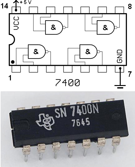
The design of TTL itself, and the use of bipolar transistors pushes you towards a somewhat specific voltage range. It’s bigger than 4.75-5.25, but you the freedom has a limit. I can show you the breakdown if you look at the 7400 schematic (this is the “original” 74 TTL, before the 74S, 74F, 74LS, … series appeared): https://en.wikipedia.org/wiki/Transistor%E2%80%93transistor_logic#/media/File:7400_Circuit.svg
A key part of TTL design is it’s output “totem pole” circuit. Two NPN transistors (V3, V4 in that schematic) enable the high or low values. The low value goes through a collector-emitter junction, which can go up to around 0.4V for high sinking currents (which allow a large fanout, desired in TTL design which was competing with RTL that had poor fanout). That gives you VOL(max)=0.4V, you want VIL to be bigger than that to tolerate some noise. On the high value you have a bigger drop: the base of the high transistor is at most VCC, and from there you have two PN junctions (on V3 and V5) to go across before reaching the output. Assuming a drop of roughly 0.7V per junction, your output will be VCC-1.4V . But if you’re driving a bit of load, you also have the resistive drop on R3. A TTL high load can’t be too big, but you could get a bit more than 0.05V, let’s round that to 0.1V. So in practice, your output VOH(min) will be around VCC-1.5V.
So far we’ve accounted for 1.9V (0.4 + 1.5), which still requires adding some margin on the low side, on the high side, and between the high/low values. You can’t just put them too close, even in a noise-free world: NPN transistors don’t toggle like a switch, instead they get quite linear in the threshold area, so you’ll have very bad edges between low and high. If you try to design a circuit that “toggles” current flow at specific voltages, multiples of the PN junction drop are natural stopping points for a threshold. You could use one drop (choose 0.7V as the threshold), and with no noise immunity between low and high you could have VIL<0.7, VIH >0.7; I guess that’s where the 2.2V (VCC=VIH+1.5V) in the patent originates. But that’s before adding noise immunity and nicer switching edges. So it’s better to choose two voltage drops as threshold. That allows to put VIL in a safe spot between 0.4V and 1.4V (with some breathing room), and VIH should start somewhat above 1.4V. (and VCC will be at least VIH 1.5). You probably could get away with a VCC of 3.5V and things will work decently…. which is what LVTTL became later. Below that it’s tricky without a very different design (assuming you stick with NPN transistors, which was a design constraint in TTL)
How far up can you go in VCC? well, looking now at the way TTL does inputs (V1 in the diagram) which is a bit of a funny way to use a transistor (using the emitter as an input) gives you a hard limit. If the inputs to this circuit are tied high directly to VCC , the base-emitter of V1 is reverse biased, and the transistor goes into reverse mode and essentially works as a base-collector diode (that’s the normal way TTL inputs operate). The base has a 3 x PN-junction path to ground (V1, V2, V4), so it will be internally at 2.1V. The emitter-base junction is reverse biased, and if you look at usual bipolar transistor specs, these junctions are usually quite weak, and breakdown at low voltages (you’ll see numbers of around 5 to 6V in transistors like the PN2222 or BC547). That will give you a hard limit of ~7-8V, and again you don’t want to operate right next to the point where your transistor catches fire. So in summary, TTL could have been designed somewhere between ~3.5V and ~6.5V VCC and probably work in a similar way.
The next paragraph is speculation, but sounds reasonable to me:
Starting from the numbers above, you could say “I need a range of at least 0.4V for low voltages, at least 1.5V for high. Let’s double those to 0.8V and 3V, giving a range of <0.8V for VIL, and >VCC-3 for VIH.” i.e. my hypothesis is that TTL chose a 2x safety factor for those ranges, somewhat arbitrarily. Then, you choose 1.4V (two junction drops) as the lowest reasonable threshold point for the circuit. That means you get around 0.6V of noise margin between VIL and the threshold (1.4V – 0.8V). If you decide to have the same noise margin above the threshold, that puts you at 1.4V + 0.6V = 2.0V. So you can set VIH from 2 to 2+3V, which gives you a VCC of… 5V :)
the morale of this story is that chatbots suck. they are not immune to the “make shit up” types on the internet. if anything they amplify them. the facts are probibly somewhere in a dusty stack of manuals in an attic somewhere that nobody bothered to scan and put online for the chatbots to read.
Plenty of the people who frequent this site watched it happen, no need to dig around in their loft for the old manual.
living memory is good (nay, superior) but ai cant index your thoughts, yet. when it does im going to make a killing selling emp devices to survival preppers.
thing about products in the pre-internet era was that paper manuals were thick, detailed, in large quantity and actually useful. id like to see an ai trained on just old scanned and ocr’ed manuals rather than indiscriminate slop. that would be a useful technical resource.
modern manuals are two pages of useless material in 300 languages. sometimes they give you a business card with a qr code that leads to a dead link if given sufficient time. rotting manuals in an attic would probibly be an improvement now. i think were in what future historians will call a digital dark age.
Single chip regulators capable of providing 1 A or more did not become available until years after 5V became the TTL standard.
One of the tradeoffs in the design of the transistors used in TTL logic is the reverse biased breakdown base-emitter voltage of the input transistors. For fast transistors, that voltage was somewhere around 5.5 (?) volts, and exceeding that voltage could cause latchup and possibly chip failure.
There was a type of bipolar logic that ran on 15 V, called High Threshold Logic (HTL). The wikipedia entry shows it as more like DTL than TTL. It was slow, so it had limited applications.
It makes many tasks exhausting. Who wants to be going along looking for information, then catch something completely wrong (often enough not even a “hallucination”, simply bad information) and spend an hour having to go over everything for similar issues.
Who wants to argue with an LLM when you can just look at source information directly?
so much this. ai seems like a complication to many an already complicated task.
It’s good to know the author was able to recognize the non-answer from an AI.
It’s also a problem that if the AI’s answer had been only slightly more direct that he might have accepted it as fact.
It’s even more concerning is that asking Google (or Bing or whatever) returns a list of pages that may or may not include AI-generated answers that aren’t identified as such.
So no matter how we arrive at the answer initially, it’s important that we follow up with references, and not simply accept a page that seems “plausible”.
My thoughts.. i am thinking 5 volts was good, as it was a nice way to get some solid headroom from a rectified filament winding transformer (of which there would have been MANY), through a basic BJT voltage regulator. Once that 6.3 vac went through either a full or half wave bridge rectifier, and its voltage drop, then into back then wouldn’t have been too large a filter capacitor, leaving a fairly messy DC”ish” rail, then through a basic zener regulated BJT series pass regulator, 5 volts seemed a nice round figure that worked out well.
To me, i think it was a legacy of the valve era, and the huge amount of transformers that only had 1 high current winding, and that was the filament winding. This was before switch mode regs were ever invented, so it would have all been linear regulators. 6 volts would have been too high, with not enough headroom through a full wave bridge, and then the drop over the series pass transistor. 5.0 just “sounded” great.
Boom, a de-facto standard.
I always assumed it was the lowest voltage that gave enough room for a couple of transistors stacked on top of each other to still work OK with enough headroom for a bit of noise immunity.
They were just planning ahead for USB
You win XD
“It also cited the development of the 7805 linear regulator in the late 1960s as a driver.”
I think it was inverting cause and effect. I remember the arrival of the 7805 and TTL had been around for some time already.
As an aside, it was during my gap year and some of the (older) engineers recalled having to design TTL logic using 7400 devices exclusively because other variants had been available. (For younger readers, all logic functions can be created using either NAND or NOR gates in combinations. A classic example was the Apollo Guidance Computer that used only NOR gates).
5v Filament transformers were readily available in the 60’s and they provided LOTS of current. Hams would sometimes leave a 5v filament transformer connected to their loop antenna when not in use to prevent ice build-up in the winter.
Theories abound. Practice is governed by what you have in your junk drawer.
An LLM will return the most likely answer (most common), not the most correct answer, unless the answer is clearly labeled as “this is the correct answer”. Unfortunately, a lot of wrong answers are also labeled that way by people who are confidently wrong and so end up fouling the training pool.
Three cheers for all the data well poisoners!
5V is extremely useful and super not hard to hit lol. Now if you had been fussing about 3.3V I would have your back, but there are so many ways to get 5V for ttl. I would have also had your back blaming the transistors themselves and poor markings or zero nomenclature at all. But man I am 5V all day around here lol. I will tell you which voltage I loathe though is the -15V often found in vintage audio. That is the most annoying thing to deal with when the rest of your world is positive voltage generally. I still see it in some of the bigger gear and yes I totally understand the concept of its use, it is just annoying to fix if that is the rail with issues. It would be fun though to see HaD maybe revisit the TTL Cookbooks of yore for some nu skool inspiration :)
as speeds go up voltages tend to go down to minimize rise/fall times. i cant imagine that being much an issue in the early 5v era when they weren’t pushing so many theoretical limits. but it explains why logic high voltages have been creeping lower and lower ever since.
Article of zero value. The author says:
–All of this seems like nonsense, the equivalent of saying, “Five volts became the standard because the standard was five volts.”–
We call it the defacto standard. There’s no need to find an engineering reason for a defacto standard.
5V was a practical measure to provide enough headroom for voltage drop across multiple transistor junctions. It became defacto standardized through the 74 series.
I’m puzzled by the variance folks report with LLMs. I asked ChatGPT (single try) “Why is the TTL voltage 5 volts?” and got a physics-driven answer (stacked V_BE headroom + noise margin + fan-out + power) that, to me, is as good as I’ve seen in this discussion. It also mentioned 5 V having been common for tube heaters, and mentions 74xx and later designs of the period standardizing it for easy interfacing—no causality inversion there that I can see.
Here’s the “in short” it volunteered at the end of the response:
“TTL’s 5 V supply arose from the needs of silicon BJTs — a few diode drops, plus margin for noise and current drive — and stuck because it worked, matched existing power rails, and became industry standard before MOS logic took over.”
Genuine question: what’s driving our “different realities” here—model/version drift, prompt framing (“engineering reason” vs “history”), sampling randomness, or evaluation bias?
maybe the userbase is divided into two groups (arbitrarily or by mined data, so the groups don’t interact too much on other channels), where one half is presented good, valid data and the other half is presented utter garbage, so the discussion between those two can later be mined for training data, or can be kept busy when things surface which are wished to go unnoticed by public (just present the unpleasant facts to the “garbage” group first, so the “valid” group won’t believe it)
Charles Kettering chose the 6.3 volt lead-acid rechargeable battery for the electric starter introduced on the 1913 Cadillac. Radios immediately switched over to 6 volt filament tubes to use the rechargeable battery, even while still using batteries for plate voltage. V8 engines required 12 volt starters and all cars became 12 volt in 1955. This produced a ready supply of cheap 6 volt rechargeable batteries, the staple in every EE circuits laboratory. 5 volts (and 10 volts) became the standard 100% of span for analog computers and process control from the 1930’s through ’60s, easily regulated down from 6.3 volts. So the regulated 5 volt supply became the standard Vcc for TTL logic.
I took this question out another door. Early relay controlled industrial equipment used 120VAC or 1 leg of three phase 440VAC stepped down. 24 volts was adopted as a standard mostly for personal safety. The rational is somewhat circular like 5 VDC for TTL. 24VAC is common for doorbells and thermostats in the home environment. Heavy equipment and military vehicles use(d) 24VDC. Telco legacy is -48VDC. My answer is critical mass requires standardization.
Reverse engineering the Roswell crash found the common voltages used in electronic circuits were 3.3, 5, and 12 volts. So if it was good enough for an advanced alien civilization…
5 volts AC as the rectifier heater voltage is an industry standard, not unique to Fender. Also, it is separate from the 6.3 or 12.6 volt supplies as, the cathode in the high tension rectifier it is typically hundreds of volts above ground.
Allow me to add zero temperature coefficient of 5V-ish Zener diodes to this adjacent-but-not-causal-factoids comments section.
This makes 5V a privileged, aesthetically superior voltage, especially for something that won’t care if it’s being run at 4.5 or 5.25 V save for minor speed changes.
Anyway, following that argument, ICs should run on 4.0V. Quoting Wikipedia:
“It is also worth noting that the temperature coefficient of a 4.7 V Zener diode is close to that of the emitter-base junction of a silicon transistor at around −2 mV/°C, so in a simple regulating circuit where the 4.7 V diode sets the voltage at the base of an NPN transistor (i.e. their coefficients are acting in parallel), the emitter will be at around 4 V and quite stable with temperature.”
This is how the lecturer explained it on my Uni course in 1971 or so:
“If you look at the circuit of a TTL gate, the output circuit looks like an audio amplifier output stage with half of the components left out. The circuit uses Vbe drops in place of resistors for biassing, an arrangement which only works over an extremely narrow range of Vcc centred on 5V.”
Pretty sure it’s 5V because USB is 5V. (duh)
Why I like 74HC chips, they are 2-6V with input levels that scale with Vcc and are nice and symmetrical.
The precursors to ttl logic get so overlooked. RTL, DTL, etc. RTL ran on 3.6v for example but there are reasons it didn’t survive. (Slow and fan-in issues, not to mention current draw) Many of these circuits that became ic chips were originally built as discrete circuits on pc boards in a time before chips. DTL was all over IBM and DEC designs but look cumbersome today due to using -6 and -6v and 0 and -12v for NPN and PNP based logic respectedly. TTL is the first logic that seemed to rely on direct input to the transistor so settling on voltage that worked best for the transistors in input and output stages used makes sense and Buie set the stage at Sylvania and everyone else followed. Recall that like 70% of all chips in the 60s were going to the military, who live by standards.
The Vebo of many bipolar transistors is 5V, and one comment I came across just now said that the process of optimising Hfe converges on this potential. I am not skilled in transistor design so cannot confirm or deny this, but it seems plausible. So perhaps 5V was chosen to be the highest voltage that would not destroy the active TTL devices, whilst maximising the system noise immunity.
Supporting this contention: I was taught to pull up unwanted TTL inputs via a resistor (2k2 was used for this) rather than a direct connection to Vcc so that any momentary spikes on the power rail would not damage the chip.
It may be relevant that the true Zener effect has a maximum around 5V. (Zener diodes above about 5.6V are actually relying on the avalanche breakdown).
As all this is speculation. I should love to know the real reason!