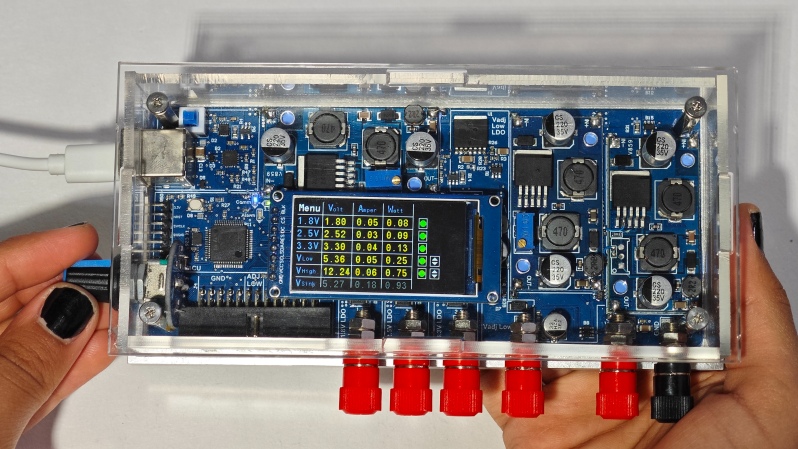
USB power has become ubiquitous — everything from phones to laptops all use it — so why not your lab bench? This is what [EEEngineer4Ever] set out to do with the BenchVolt PD USB adjustable bench power supply. This is more than just a simple breakout for standard USB PD voltages, mind you; with adjustable voltages, SCPI support, and much more.
The case is made of laser-cut acrylic, mounted to an aluminum base, not only providing a weighted base but also helping with dissipating heat when pulling the 100 W this is capable of supplying. Inside the clear exterior, not only do you get to peek at all the circuitry but there is also a bright 1.9-inch TFT screen showing the voltage, current, and wattage of the various outputs. There is a knob that can adjust the variable voltage output and navigate through the menu. Control isn’t limited to the knob, mind you; there also is a Python desktop application to make it easy changing the settings and to open up the possibility to integrate its control alongside other automated test equipment.
There are five voltage outputs in this supply: three fixed ones—1.8 V, 2.5 V, and 3.3 V—and two adjustable ones: 0.5-5 V and 2.5-32 V. All five of these outputs are capable of up to 3 A. There are also a variety of waveforms that can be output, blurring the lines between power supply and function generator. While the BenchVolt PD will be open-sourced, [EEEngineer4Ever] will soon be releasing it over on CrowdSupply for those interested in one without building one themselves. We are big fans of USB PD gear, so be sure to check out some other USB PD projects we’ve featured.


Nice, thank you for sharing! Been looking for the amateur-level stable bench power supply for some while, maybe this will do just nicely.
IMHO, finally, someone figures out that signal generator AND regulated power should have been a standard some long, long time ago (in a galaxy far, far away, where designers work with customers directly, unimpeded by the marketing department fantasies).
Thanks.
You’re welcome (I was at least one of the people who sent this in lol)
Lots of time spent on making it look good while inside it uses the worst, cheapest switching power supply modules from AliExpress which tend to break and burn just from looking at them. A perfect YouTube project.
This is a prototype unit, and on-board DC-DC converters will be used in the batch production. The device offers excellent voltage, current, and temperature monitoring features, and it has been tested for over four months so far.
If you follow the project, I’ll also be doing some heavy stress and durability tests soon — then you’ll see how robust it really is.
Also, everything is open-source, my friend — you can repair any part yourself or even upgrade the project if you like!
The problem isn’t that the modules are poor quality, it’s that the design is extremely old. There’s a reason these modules are widely available and cheap, it’s because there’s a massive surplus of old XL6009 chips that nobody else wants.
It’s fine if you want a box filled with cheap and noisy regulators. Not great if you care about the noise and ripple on those outputs (and to be fair, some people don’t.)
Hello thanks for your valuable commend. There is two think here one is there is many other dc dc converters like XL6009 and on production it is not finalized that which componenet will be used at the end, currently i have tested with 2-3 different converters. The other think is there is LDO after DC DC converter and voltages are changed by LDO margining DAC. I am not saying that this power supply has worlds lowest noisy power supply but it is really enough for many applications and better performance than most of the competators. The aim here is having portable and flexible Multi channel supply at low cost and open source for everyone.
Yeah, for those interested, these are modules based on the XLSEMI XL6009 Buck/Boost DC/DC converter chip:
https://www.xlsemi.com/datasheet/XL6109-EN.pdf
Sorry, this datasheet : https://beriled.biz/data/files/XL6009.pdf
Can someone please counter this with good reasoned arguments?!
Because when I saw the image and looked closer I came to a similar conclusion and that’s a bit depressing (the existence of the video at all + that it was featured on HaD).
This is a prototype unit, and high quality tested on-board DC-DC converters used in the batch production. The device offers excellent voltage, current, and temperature monitoring features for reliablity and it has been tested for over four months so far.
If you follow the project, I’ll soon be running heavy stress and durability tests — so you’ll get to see just how robust it really is.
The project is fully open-source — everyone will have access to it. Complete instructions will be provided so that anyone can easily repair, modify, or even upgrade the project themselves!
In electronics, if something fails, it usually means you are exceeding the electrical specifications of a component or not cooling it properly. With good engineering, creating a reliable design isn’t actually that difficult.
In electronics, if something fails, it usually means you are exceeding the electrical specifications of a component or not cooling it properly. With good engineering, creating a reliable design isn’t actually that difficult.
What could possibly go wrong?!
Man like 10 years ago i got an oscope and a bench supply that each had (roughly) one knob per function. i’m never going back. People talk about all of these specs and features and it turns out, that’s the one i care about on my bench
The knob is not the only way to make adjustments — there’s also a Python-based UI that lets you control everything.
The knob is not the only way to make adjustments — there’s also a Python-based UI that lets you control everything.
Yeah, let me just plug that into my laptop and drive the voltages!
He’s showing it with nothing under load. Unless it’s programmed to shut down past a certain current level it’s a fire hazard waiting to happen.
can’t say I like the interface. Too small and with the knob…as mentioned above “what could possibly go wrong”
Hard Pass
The device offers excellent voltage, current, and temperature monitoring features, and it has been tested for over four months so far.
If you follow the project, I’ll soon be running heavy stress and durability tests under load — so you’ll get to see just how robust it really is.
The project is fully open-source — everyone will have access to it. Complete instructions will be provided so that anyone can easily repair, modify, or even upgrade the project themselves!
The system continuously monitors parameters like instantaneous current flow, overvoltage, and temperature. The MCU only allows power delivery over PD when everything is within safe operating limits — so risks like overload or fire simply don’t exist.
The components are thermally optimized — using many vias and a thermal pad to efficiently transfer heat to the aluminum base below. This allows the device to operate under load while staying within safe power limits.
Temperature is also continuously monitored. I’ll be sharing some under-load test videos soon — thanks a lot for your feedback!
Beyond everything the author wrote already, it’s worth pointing out that this is of course a USB PD sink, taking its power from a USB PD source, which itself already provides overcurrent protection.
This… has a lot of concerning issues given that you could be supplying a lot of current.
The adjustable output 1 uses an LDO, but it follows a super-basic totally unshielded switcher, and that is not easy to make low noise. It’ll cut down on the ripple, sure, but noise is more than ripple and without a doubt the switching transients will cut right through the LDO. Which isn’t easy to measure either.
The overall physical architecture just doesn’t work for low noise either. Just trace the input and return current path for the adjustable output: the input’s gotta flow along the top, which is going to be right under where the LDO is, so you’re not going to get the full PSRR from the LDO just due to the ground currents.
There’s another subtle issue too: you’ve got a bunch of separate outputs + a single ground at the end. And you’re talking about supplying like 10+ amps there. Think about that last power supply closest to the ground output. It’s normally sitting there seeing like 5-6 amps coming in the ground connector plus its own. And then at some point you unplug the first supplies… and all that current disappears and you get a shift due to the overall finite resistance. Single ground input just doens’t make sense when you’ve got multiple outputs and that much current.
Hey, really appreciate you taking the time to dig into the details — that’s the kind of feedback that actually helps projects move forward.
You’re absolutely right about the grounding and current return considerations. Adding an extra ground terminal or local return paths for each channel would definitely improve the overall current handling and minimize voltage shifts across high-current traces.
Noise-wise, yes — a single LDO after an unshielded switcher won’t magically remove all transients. The current setup already includes RC filtering and ground-plane isolation between channels, but there’s still room for refinement, especially for people who’ll use it in precision setups.
That’s the great part about open hardware — every iteration can get a bit smarter based on this kind of insight. Thanks for pointing it out!
Even without high currents, single GND is simply inconvenient. Imagine you want to power several devices, each with its own GND wire, and you only have one GND socket on PSU. Very bad design choice in my view.
The device offers voltage, current, and temperature monitoring features for reliablity, and it has been tested for over four months so far. If you follow the project, some heavy stress and durability tests coming soon. Also, everything is open-source anyone can repair any part yourself or even upgrade the project if you like!
I’m not sure why we should take the claim seriously. The project page appears to simply dissimulate, with “Open Source: – Python UI – Firmware – Schematics”, and then comments asking for schematics and being told they would be released “soon”, almost a year ago (of note to those wondering about noise: there are also comments expressing disbelief at the large amount of noise shown there). The maker even brazenly states “This project is completely open source, including hardware, firmware, and the GUI, so it’s accessible to everyone.” in Dec 2024, while not releasing anything.
The crowdsupply page, under a large “Open Source” heading, claims the project “is open-source”, then gives details that are clearly not open source: no sources are available, but they “intend” to make sources available “after supporters receive their products”. Finding any more information is a bit difficult; the maker’s website doesn’t actually exist, for example.
The HaD reporting quietly changes the claim to one that is not simply wrong, in pointing out the the project is not open source, but will be in the future, if the maker’s claims are to be believed. But given the dishonest way this appears to have been expressed throughout the project, it is difficult to trust that the sources will ever be available.
This is a prototype unit that will utilize on-board DC-DC converters during mass production. The device provides exceptional features for monitoring voltage, current, and temperature, and it has undergone testing for more than four months.
If you keep an eye on the project, I’ll soon conduct rigorous stress and durability tests, showcasing its true robustness. Additionally, everything is open-source, allowing you to repair any component yourself or even enhance the project if you wish!
I’m sorry to hear that you feel this way. As you can imagine, completing a project like this takes time. If you look at many other projects on Crowd Supply, you’ll see that it’s quite common for the design files and code to be released gradually during the campaign process.
The project has been live on Crowd Supply for just about a week, and I’ll be releasing the block diagram, schematics, and both the Python UI and firmware code before the campaign ends. I have to do that anyway — there’s nothing to hide here.
I’m honestly not sure why it gave the impression of being secretive; that was never the intention. This isn’t some overly complex or unachievable project. As for the output noise you mentioned, I’ll be sharing proper measurements under load soon ( in 30-45 days)
Since the entire project is being handled by a single person, some details naturally take time to prepare and present. I’m sorry if that caused any disappointment.
https://www.youtube.com/watch?v=wyJbAp0etwM
Maybe this video will help you better understand the project.
While I think the critiques are a little hard whats starting to become alerting is the same defense coming from like 3 different usernames
EEEngineer4Ever
Süleyman Yasin Dundar
syd_
I’m a member of Hackaday.io, but when I first tried to comment there, my comments didn’t appear. I tried several times and wasn’t sure why, but after a while my posts started going through. That’s why you have seen different names.
I only know to speak formal english dude, learned from the school :=)
Next time before you record a video please shave have your… hands. That’s disgusting.
Thank you for your seciencetific comment.
Not sure what I enjoy more, the thoughtful testing being done or the professional wit of your responses. Keep up the good work.
Cool project dude thanks for sharing. Ignore all the trolls and haters. They just sucking air.
If you’re going to front a project you have to have thick skin, if not the naysayers will get to you.
The comment section is filled with cheetle dusted neckbeards with questionable bathing regimens. I’m sure the appearance of his hands will go largely unnoticed.
How is the number of point is 1024 but turn out to be 12 bits? Typo or something that we dont know about?
Number of points and resolution are different things think again ;)
How It Works
When BenchVolt PD powered on, all regulators and converters start in the disabled state. The STM32 microcontroller first powers up and performs safety checks by monitoring temperature, current, and voltage. It then enables the DC-DC converters, followed by the linear regulators in sequence.
Throughout operation, the MCU continuously monitors system all parameters to maintain safe operating conditions.
An additional safety layer can be used by setting a power limit through the USB PD interface, ensuring the system never exceeds the predefined power threshold. This limit can be configured either from the device’s on-screen menu / rotary encoder or through the Python control interface.
Each DC-DC converter is monitored to ensure no more than 5 A is drawn from its output. The 1.8 V and 2.5 V LDO regulators share the same 4 V / 5 A pre-regulator rail, while the 3.3 V and Adjustable (0.5 V – 5.5 V) LDOs share the 5.5 V / 5 A rail. Therefore, when both LDOs on the same rail are heavily loaded, their combined output current should not exceed 5 A total (typically below 3 A per channel).
The third buck-boost output (2.5 V – 32 V) operates independently and can deliver up to 3 A. However, due to the limited size of the inductors and capacitors, the output ripple increases as the load current rises. Despite this, the other outputs driven through LDOs provide significantly lower ripple levels, ensuring clean and stable voltages for sensitive circuits.
Note:
In theory, the system is capable of delivering up to 100 W of total power. However, due to conversion and regulation losses within the DC-DC converters and LDOs, the full 100 W cannot be drawn simultaneously from all outputs. The design goal of this project is to provide a compact, portable, multi-channel power source that delivers sufficient power for a wide range of applications.
The maximum achievable power depends on the connected USB PD adapter — for example, a 65 W charger will cap the system power at 65 W.
Project is live on Crowdsupply
https://www.crowdsupply.com/fusionxvision/benchvolt-pd
Here is the first upgrade; BenchVolt PD is now significantly more efficient thanks to TI’s TPS55289 DC-DC converters. More improvements are on the way, so stay tuned!
https://www.crowdsupply.com/fusionxvision/benchvolt-pd/updates/from-prototype-to-final-design