The Commodore 64 has, by modern standards, the interesting power requirement of needing both 5 VDC and 9 VAC. Traditionally, one would use an iron-core transformer to step-down the wall current — be it 220 V or 115 V, 50 Hz or 60 Hz — to produce the low-voltage AC.
That’s how Commodore did it, and that’s how most of the aftermarket replacements do it, too. That iron-core transformer is bulky, though, and [Side Projects Lab] decided that in this day and age of switching supplies and USB-PD he could surely do better. Which he did, with the diminutive PD-64.
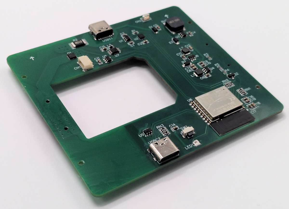
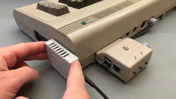
As you can see, it just covers the power port of the C64, and not much else. Partly that small size comes from offloading some of the hard work onto a USB-PD wall wart. The PD-64 requests 12 VDC, which it then steps down to 5 VDC with the usual buck converter, and inverts to 9 VAC in a circuit that is the most interesting part of the project.
There are various ways one could do this, after all, and we’re sure some of you will have different ideas than [Side Projects Lab], but his method seems sound. In order to provide galvanic isolation between the two outputs, the 12 VDC line is first chopped into a 500 kHz signal, and run through a tiny 5:6 ferrite transformer. That output gets rectified to 13.6 VDC, a voltage that is used to run a class-D audio amplifier to produce the 9 V peak-to-peak, zero-DC-offset signal the C64 needs.
[Side Projects Lab] has released both FreeCAD files for the case and STLs as BY-CC-ND 4.0, and a circuit diagram is available for the electrical side. If you don’t want to design your own PCB, [sideprojectslab] will be selling finished versions.
If you’re interested in further dragging your C64 into the modern era, check out the HDMI output that [Side Projects Lab] hacked together for the iconic computer last year.
Continue reading “Tiny C64 PSU Rejects Tradition, Embraces USB”