As Ethernet became the world-wide standard for wired networking, there was one nagging problem. You already have to plug in the network cable. But then you have to also plug in a power cable. That power cable needs to be long enough. And have the right plug on it for your country. And provide the right current and voltage. That’s how Power over Ethernet (PoE) was born, first in a veritable Wild West of proprietary standards and passive injectors, then in a standardized process. Recently [T. K. Hareendran] wrote a primer on PoE, with more of a DIY intro focus, including some favorite PoE PD (powered device) chips to use in your own design.
You can still totally use passive PoE if that’s your jam, and you have full control over the network and any connected devices. This would allow you to, for example, power your SBCs for a couple of bucks, although for adding PoE to your Mac Mini you may want to look at some more refined options, if only as a safety precaution.
Much depends on the needs of each device, as PoE is meant mostly for low-power devices such as VoIP phones and the like. The more common IEEE 802.af and .at standards (Type 1 and 2) cap out at 30 Watts, with about 25 Watts available to the device after losses, while 802.3bt (Type 3 and 4) takes this up to 90 Watts, or just over 70 Watts after losses. Before making a decision, it would be good to read a detailed guide from someone with experience, like the one by [Alan] that we covered a while ago.


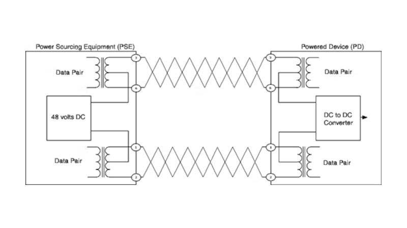
Is this AI-generated image? DC current won’t go through transformers, just heat them like it’s a big old resistor.
Take a good look at the diagram before making any criticisms. If you put as much effort into understanding as you do into complaining, you would see that the power supply passes through the center tap of the transformer’s secondary winding. What’s the problem? When you don’t know or don’t understand something, you keep quiet instead of acting like a know-it-all. You’re talking nonsense.
Well said.
“I don’t understand this”
“Therefore it must be wrong”
Blinkers on full.
No, that is how it’s done. As you see the DC is connected to the middle connection on the windings on the ethernet phy side. This means it gives a DC bias to the signal. That is no problem as those are differential pair.
You are mostly virrect, but there is no resulting DC bias, because the DC voltage is applied equally to both sides of the pair ,, so balance of the pair is maintained. You can even simplex another voice circuit to the physical pairs. Each “pair of pairs” csn provide an additional “phantom” circuit, resulting in a 50% pair gain, using no wire, and causing no interference to the physical circuits. Thr users don’t even know there is an additional “hitchhiker” riding on the system, because there is no bias caused by superimposing DC OR voice traffic. Credentials: former T1 Carrier phone nsn here.
well analyzed and well said guys! 😎👍
DC will pass through the transformer windings as shown here, but not between transformer primary and secondary sides.
Other than using the unused pairs in my private 100Mbit cabling, is there any super cheap way of getting just 12V and a little current through?
rs232 DE9 serial mice didn’t have a dc pin in the plug, but they still managed to operate through use of charge pumps.
And I always thought they were stealing power via diodes/from the data pins..
You can try buying a PoE switch where just the PoE part is broken and insert voltage manually in selected ports (transformer’s center pins).
Or you can take a part any normal switch and get lucky that the magnetics (transformers) have unused center pins (this is just a wild guess).
Why would you want to?
If its only 100 then just use the spare pairs.
Why on earth make it more complicated.
If the device isn’t poe and your switch is, you can get break out devices on a variety of voltages and connectors.
My rpis are all powered this way cos the poe hats don’t make financial sense.
The DC current doesn’t go ‘through’ the trasnfomrer, the current goes from from the source on the left side to the middle tap of the winding an from here outwards through the winding of the the transformer, the asymmetic splitting of the DC current doesn’t produce a net magnetic field in the trasnformer (no bias). I can’t see a problem.
The data sure will its a squarewave. And they are the impedance matching transformers that connect the unbalanced 100ohm Ethernet wire to the unbalanced internal circuitry.
They are sometimes called “Ethernet transformer”, baluns (not often used in Ethernet but correct) Ethernet Magnets. There is 4 of them in your typical black rectangle.
Do s little research on “simplex” or “phantom” connections, which the telephone industry has been using for over 100 years to get power to remote devices like line amplifiers, aka “repeaters”. It works and it works well. Let google be your friend.
Show me AI which can draw even simple battery-switch-lamp schematic. I really cannot find any.
Sure! Chatgpt “Draw a picture of a complete circuit with a battery, switch and lamp”
It’s on the center tap of the xformers.
There is zero issue with using an enforcer like that to transfer both dc and differential mode.
This works fine, you need to take a better look at it.
So many replies mention that the dc cancels out as it goes through to opposing windings. Have implemented similar designs with audio through transformers, and DC power and RS 232 comms through the centre windings. Worked in that system. Read up on how transformers work.
Observe the modern Luddite: Anything they can’t comprehend is clearly faked by AI.
Aaand ? If you look at the image again, you can see the current is connected on the ‘OUT” side of the transformer, and is removed from it also at the OUT side.
I don’t understand it but it gives “fake af” vibes.
Nope, it’s real, and has been used by the telephone industry for well over 100 years. It’s how the power the remote T1 Carrier repeaters in the field. Look up “simplex” or *phantom” circuits; its actually as simple as a doorbell. Let Google be your friend.
As a retired phone guy, maybe 50 years ago, I came across this while planing to replace some of that interesting wiring setup to use buried cable. I think it only had 4-party lines. I also think we called that type wiring as “bug-bear” wiring.
Please correct any errors I may have remembered incorrectly. Thanks
(In Mechanicsburg Indiana)
i’m not sure if you’re going by vibes or if the substance of the circuit itself weirds you out. But i’ve definitely noticed as i try to understand circuits outside of the very narrow range that is familiar to me, i often have this feeling. Definitely at first glance, this circuit looks pretty implausible too.
Like the extreme example is the magnetron – it’s just a short circuit! Might be fun to catalog all of the quite basic and common circuits that nonetheless give off a “this is fake” vibe if you know just enough that it feels like it “ought to make sense” but doesn’t until you connect the dots.
If you don’t understand something, you’re not exactly best placed to judge it’s validity.
HaD doesn’t post garbage in general, so the default position should be that something is correct unless you know for certain that it doesn’t make sense.
We make mistakes same as anyone!
But yeah. Transmitting DC through the common mode on (two) AC circuits is how PoE works.
Semi-related, that’s why RJ45/cat-5/cat-6 wires are colored in certain way – brown/white-brown supposed to be injected ground/negative, blue/white-blue supposed to be injected positive.
In the past I didn’t bother with the extra-steps (obtaining RJ45 jacks and soldering them to the boards, so the store-bought cables can be used) and just made my own cable that would split off the brown/white-brown and blue/white-blue wires into 12v plug and jack : – ]
Worked so far, since the distance is well within specs (I’d say ~24 feet in total), as cheap as it gets.
Even less related, but bear with me for a minute or two : -] (loose thoughts will follow – feel free to discard)
I long wondered “why are there no dedicated low-power universal plug that would deliver under 100 watts variable voltage and power, AC or DC?” Most low-power wares that need a dedicated wall wart would be just right to these?
My thoughts were “if there exists a simple and robust solution that would second-simplest to the barrel jack (remember the times when the size of the barrel jack signaled the voltage?), but smarter?” Furthermore, make it so it is either flat or has tony knobs so little kids can use them with the risk of being zapped?
I even sketched out the design, square receptacle and square plug, basically, you hang the plug on the receptacle, and the moment it clicks, it does the instant handshake that decides what power is being delivered. Since the plug is square, it could have not just two, but four or six pins (or more), hence approaching the venerable RS232 (keep in mind this was late 1990s) and, potentially, VGA, too. The logistics were quite simple, really, the plug would have a built-in “signature” passive analog circuit that the receptacle would “read” and set itself accordingly. Nothing major, really, an op amp or two would read the thing and power up PWM delivering such and such voltage limited to such and such amperage. Oh, I never got around to properly designing the thing, but the idea was stuck in my mind ever since.
Wait, you lost me at RS232/VGA. You want to run power in parallel with data? Even low-voltage power can’t carry any meaningful wattage without inducing horrible EMI in the data lines, unless you engineer in special precautions. PoE (and USB-C) escape it by making clever use of twisted-pair data lines. Powerline Ethernet goes the opposite route, by encoding the data signal INTO the power lines.
But older analog data cables like VGA and RS232 had no such protections. In the general case, the wisdom is that power and data need to be carried over completely separate cables, and only cross (if they must cross) at 90° angles.
Used to get 9pin dsub hoods with an rj45 built in for building custom serial cables.
Putting in a 15pin for vga then having the ability to run via over structured wiring was better than spunking a lot for the special longer length cables and trying to snake the ends through the walls.
Back in the day….
RE: Bob, yep, I moonshined as a cable tech for some year or two (1993 or 1994, I think). We did just that, semi-independent custom cable makers. We did them all, coax, IBM, depending on what clients wanted. RJ45 was what paid the best, since everyone was suddenly going “everything HAS to be ethernet”, and, coincidence has it, telephones powered over ethernet were in high demand as well.
RE: FeRDNYC, yep, sounds like it was the powerline ethernet that I was thinking of/about. Coincidentally, the post was about powerline ethernet.
My 1990s thought was “juicy wires for the power, thin wires for the data”, and yes, EMI will be the problem, twisted wires can only cancel out that much.
It was a half-baked idea, of course, but the thinking was “majority of the appliances – other than ovens or irons – won’t need much power to start with”. I haven’t thought pass that, but perhaps two or three different similarly-looking receptacles would be needed, similarly how we have grounded and not grounded power plugs (and then there is a dedicated three-prong jack for electric ovens that run off of 380 AC).
Scaling down the runaway thoughts, probably an upgraded/revised USB-A is good enough for what I was thinking. Seeing how some RaspPis have two separate USBs (RaspberryPi Zero 2W to be exact – one USB is a dedicated power), probably that’s the simplest solution, two USB-As, except a semi-flat plug using spring pins.
My idea was “flat plug that will be wide enough so little kids connecting one to the receptacle won’t be able to touch the power contacts”. Now that I think of it, perhaps this is overengineering, if the said handshake ONLY happens after confirmed click/contact, the plug is already in the receptacle, hence, the contacts delivering the power are already out of reach by tiny fingers.
Those with little kids know quite well how important to have ALL contacts of any kind out of reach. Because it is a matter of when, not if, that those tiny fingers will find a way to grab onto these. Hence, square plug with short stubby contacts that are far away, wide plug, tiny contacts inside.
Back to the second kind I was thinking, sealed inductive loops, no contacts at all, and if the plug is large enough, maybe there is a way to push more than 100 watts AC, ethernet included. Kind of like a 1:1 transformer of sorts. I’d still keep few pins for the the initial handshake, though, because that’s as simple as it gets.
But wait, there is more.
I am looking at this thread/topic, and thinking “man/boy/bob-is-your-uncle, this had already been thought of and implemented, though, indirectly, not the way I thought it should have been done”.
RJ45 is not the best jack around, since the pins are not built to deliver juicy currents, but the circuit is close enough to what I was thinking! With some commandeering/rethinking around this just might do. What’s missing is the plug/receptacle designed the way that would have enough pins to deliver power under 100 Watts, plus some other extra pins just in case; since everything is now digitized, there is no longer a need for separate dedicated pins for, say, speaker wiring, sound can travel over, say, S/PDIF feeds. No, not fiber, digital signals over the wires.
Now here comes the best part. Since the plug was thought to be square, I thought that it should also include the inductive coupling loop running along the perimeter. Because it can also double as the wireless charger – and now there is plenty phones that can do that : -] Actually, the idea was “the moisture-resistant solution for boats should be a SEALED receptacle that maybe has two or three inductive loops – no pins – and there are some kind of plastic “guide posts” that make sure it clicks in the orientation needed”. Obviously, since it is a square, four different orientations might do.
Back to the drawing board, I may have an idea worthy wasting the rest of my weekend.
I like your train of thought Sammy Gee. But 802.3 is what everyone is building off of. Kind of like the whole USB PD. Both of these things seem sub optimal but they are good enough. Adoptability is the key.
In the case of the IEEE in regards to everything and 802.3 they are very aware of the regulations attached to the National Electrical Code. So a lot of this has to do not what is possible broadly speaking but what is possible within constraints.
These constraints include the NEC which is the regulatory body everyone in USA is expected to abide by AND adoptability. 802.3i-1990 still works with many if not most switches today, and I found recently that there are brand new “Cloud optional” products that expect you to have 802.3i with 802.3at, PoE standard introduced in 2009…
What company was that you ask? 2n, they make nice endpoints but sometimes their default software configuration is downright silly, they fixed it to support 802.3u-1995 “100BASE-T”, it was turned off in software.
The reason they “seem sub-optimal” is that they are designed to support a far larger application space than is obvious to a single user. That flexibility means that they are rarely the easiest or nicest solution for any particular device, but they are “good enough” for many more things.
The “optimal” solution for a specific application would end up being nearly or completely unusable for everything else.
RE: damntech – thank you for pointing out the IEEE and NEC standards rabbit holes. Might as well touch-up on my (mostly ignored) knowledge of these.
I am honestly quite skeptical about “everything HAS to be in the cloud” part; in the 1990s when I first thought about such universal power/data plug, it wasn’t exactly invented yet (though, I lied – AOL was already around, so were all kinds of dialup online communities, too, BBBs, etc). The circuit will have to be as simple as a wall wart, cheap enough to be produced in any part of the world, and include only parts readily obtainable at the (back then – 1990s) local Radio Shack. Op amps and FETs, obviously.
Yep, the final solution may end up being only one-time use (my house) and nowhere else. I kinda already have few hacks around working despite standards (custom-made ethernet cable that splits off power lines), so for it is pie in the sky kind of deal.
You do know there are two color schemes 586A & 568B
AND
at least three different pair combinations to transfer PoE power!!!!
100BASE-TX spare pairs (unused).
100BASE-TX data pairs (unused).
all four pairs.
correction:
100BASE-TX spare pairs (unused).
100BASE-TX data pairs.
all four pairs.
TI-586A and TI-586B aren’t really color schemes, but rather pin-mapping schemes. They both rely on the same standard color scheme for a 4-pair cable. (Brown, ora
…nge, green, and blue, each in a twisted pair with a white-striped version of same.)
Yeah, okay
would have been better. (not to mention that the 2nd set of pairs have the same colors in both schemes)
Caution to all designing POE devices.
See this app note about the necessary protection to keep the POE from nulling the ethernet PHY.
Fundamental problem is that the connectors may momentarily be partially connected during disconnect putting a big voltage across the transformer.
https://ww1.microchip.com/downloads/aemDocuments/documents/OTH/ApplicationNotes/ApplicationNotes/00002157B.pdf
As more and more POE stuff hits the network, including lights and cameras, there’s going to be issues with heat dissipation on the wires, particularly when you’ve got less highly trained installers who may not think about this issue. I can’t find a cite offhand, but at a conference someone was claiming that they managed to take a big thick bundle of cables and pipe a bunch of POE through many of the cables and the conductors in the center got warm enough to start causing damage to the ethernet cable sheathing.
There isn’t an issue, I have 24 AP’s averaging about 18W each all in one bundle zip tied together in a cable tray running from one end of the racks to the other about 25 feet. I’ve inserted a multimeter temp probe into the center at multiple points, barely above room temp.
Admittedly this is in a quite well cooled server room but seems typical as generally you start to fan out devices an not have a bunch of stuff in one place to be running POE to.
This is an imagined problem, not a real one.
In my foolish youth, we cooked up a DIY version of PoE, where we’d just run it through the unused pairs, skipping all of this unsavory transformer stuff. Ground wire, hot wire in a pair.
Of course, we only needed 5V on the far end, so we didn’t bother with all that 48V up/down-conversion. And then ran this power over a fairly long ethernet cable.
P = I2R is real.
We got like 3.5V out on the other side…
This sounds wrong to me. They had to put a lot of current through it. The reason I say this is I live in CNY and one cold winter day got tired of sitting on a swat that was colder than ice. So, after some farting around I decided to try with a dead 50” cable from work. To be honest, I kind of had this in mind when I took the dead cable. It had died right at the connector like they usually do, but I did not want the connectors anyway. First pass was to take the cable and make it so it was one big loop so all the strands are in series. Take the end pair and hook that to my bench supply and fire it up to 15V and see what happens. Very very little, so go to the far end and take 10 feet off, try again. That time after a few minutes you could just start to feel the weather get ever so slightly warm to the touch. I took 5 more feet out (which is really 40 feet of one strand). I brought the two ends of the cable together in the center and used the center as the center of a spiral, that turned out to be near butt sized when it was done. I wrapped that in duct tape and tried it on the bench supply and that seemed happy enough and got mildly warm in a few minutes. So I got a lighter plug, and my car seat already had a slash in it. I had big ideas of pwm and thermistors and high tech stuff, but honestly, it was just so damn nice I never went back to it. I did to make sure to unplug it when not in use, but it made winter commutes a whole lot more tolerable until the engine in it died.
I figure that was a pretty good stress test. On very long rides my butt might get a bit too warm but unplugging it was easy enough. I never even once got a whiff of melting plastic and I worked at a place that had a lot of melting plastic so my nose was very attuned to that smell.
Some years ago i was hoping for a PoE charging ThinkPad… and they gave me a ThinkPad without Ethernet at all. :-(
Has anyone built a PoE -> type C charger yet?
This is a fantastic introduction to Power over Ethernet. I appreciate how you broke down the differences between passive Poe and the standardized IEEE 802.3af/at/but options it really clarifies which devices can realistically use Poe. The note about wattage losses is especially helpful for anyone planning to power multiple devices. Great read for both DIY enthusiasts and pros looking to simplify cabling.
Wow this is such a thorough overview of Poe. I really appreciate how you break down the evolution from the “Wild West of proprietary solutions to the standardized IEEE 802.3af/at/but formats. It is great to see practical advice for DIYers too especially the caution about passive Poe with sensitive devices like a Mac Mini. I have used Poe for some VoIP phones and wireless access points and it is amazing how much cleaner setups can be when you eliminate extra power cables. Thanks for the detailed explanations and references to additional guides super helpful for anyone considering building or upgrading a Poe network.