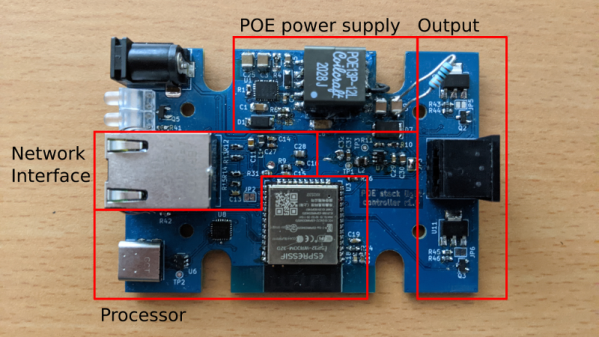
As Ethernet became the world-wide standard for wired networking, there was one nagging problem. You already have to plug in the network cable. But then you have to also plug in a power cable. That power cable needs to be long enough. And have the right plug on it for your country. And provide the right current and voltage. That’s how Power over Ethernet (PoE) was born, first in a veritable Wild West of proprietary standards and passive injectors, then in a standardized process. Recently [T. K. Hareendran] wrote a primer on PoE, with more of a DIY intro focus, including some favorite PoE PD (powered device) chips to use in your own design.
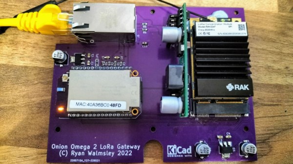
You can still totally use passive PoE if that’s your jam, and you have full control over the network and any connected devices. This would allow you to, for example, power your SBCs for a couple of bucks, although for adding PoE to your Mac Mini you may want to look at some more refined options, if only as a safety precaution.
Continue reading “Entering The Wild World Of Power Over Ethernet”