You know those old cliche that the younger generations have begun to cynically despise: “follow your dreams!” “You can be anything you put your mind to!” — well, perhaps they are true on occasion. For instance when [rctestflight] had PCBs that dreamed of becoming a hydrofoil, he found a way to make that dream come true.
It’s kind of obvious in retrospect: printed circuit boards are made of FR4, which is a form of fiberglass, and you know what else is commonly made of fiberglass? Boats. So yes, the material is suited for this task. The fact that solder joints hold up to use in a little remote-control hydrofoil is less obvious, but good to know. It certainly makes for easier assembly for those of us who have developed an allergy to epoxy.
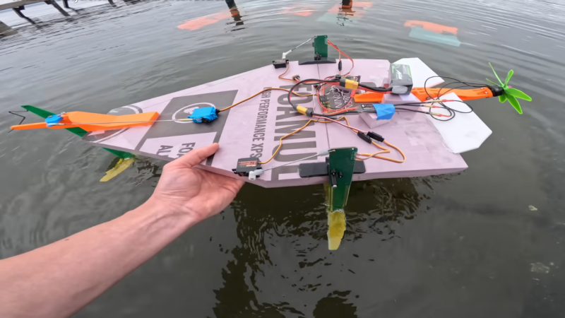
Ease of assembly wasn’t really the point here: the point was that by making the “mast” of the hydrofoil out of PCB– that’s the part that holds the underwater wing– [rctestflight] figured he could (shock!) print a circuit onto it. Specifically, a liquid-level sensor, and because microcontrollers are so cheap these days he went the “total overkill” route of embedding an ESP32 on each mast. He started with a resistive sensor, but since those self-corrode too quickly, the team switched to a capacitive sensor that doesn’t need to form a galvanic cell in salt water. Come to think of it, that might still be a problem with the solder joint between the PCBs. Good thing nobody will be riding this one.
Having such a sensor and brain close-coupled allows for a faster control loop than the sonar [rctestflight] had previously been using to control his hydrofoil’s altitude.. Pivoting each mast with its own servo made for a smooth flight over the water— well, once they got the PID tuning set, anyway. Check it out in the video embedded below.
We’ve seen PCB used for enclosures before, and even the chassis of a rover, but using it for a hydrofoil is a new hack.


‘The younger generations’ invented cynicism!
Just ask them.
WTF is up with the middle school purple prose in hackaday articles.
Do they have minimum word counts, like HS papers, have to pad it out a bit?
Paid by the word?
Protip.
Margins and fonts for padding.
Brevity for writing, remove all redundant and useless words, sentences and paragraphs.
‘PC boards dreams’??
Don’t anthropomorphize PC boards, they hate that.
One of my “favorite dislikes” about technical descriptions. Type all day and say little to nothing. It’s an acquired ability. I was fortunate to have a great tutor.
Agree
Yeah, too much prose- it wants to be a hydrofoil, it DREAMS of being a hydrofoil, it ISN’T a hydrofoil (the pcb “wings” do not a “pcb hydrofoil” make. A car has tires that fulfill much the same function: do we say the rubber wanted to be a car, and that the car is made of rubber? Sounds ridiculous, right?
Huge lede buried here! This is a v1 prototype that was finished months ago. Stay tuned for v2 where he and his team work with a factory to produce these as a kit toy!
It’s better to sense capacity than resistance. You can cover the tracks with coverlay to prevent rusting by electrolysis and contact with water. Since water has permittivity around 80, it’s quite easy to sense. Due to the high permittivity of water, the capacitive approach is not nearly as sensitive to ion concentration and movement speed as the resistive one. And you can detect the capacity change even at microwave frequencies, so you can speed up the measurement rate significantly and thus speed up the feedback loop (or make it more stable).
Back in the sixties, alternating current was used to minimize corrosion through a transformer, with a simple thyristor and a relay as the detection element. If they wanted to use the resistive system, they only had to generate a square wave, couple it with a capacitor, and rectify the signal from the sensor—just that simple. It’s sad to see the knowledge of the new generations.
You realize the guy who posted the video mainly does ME projects? Guarantee he knows a lot more than you did at that age, with more experience. Being from an older generation, how did you forget what it took to learn so much? You weren’t born with it. Now yes, i was thinking the same thing, conductivity sensors typically use AC for that reason, but capacitive sensors are just the better choice regardless, as he shows in the video. Typical Hackaday commenter.
Neither read nor watched: sponsored by PCB manufacturer?
The solder joint could be made significantly stronger by having the slot through-plated, so that the solder spreads over the whole thickness. Also a few vias keep the copper better attached to the FR4.