Recently, [Edward Schmitz] wrote in to let us know about his Hackaday.io project: SigCore UC: An Open-Source Universal I/O Controller With Relays, Analog I/O, and Modbus for the Raspberry Pi.
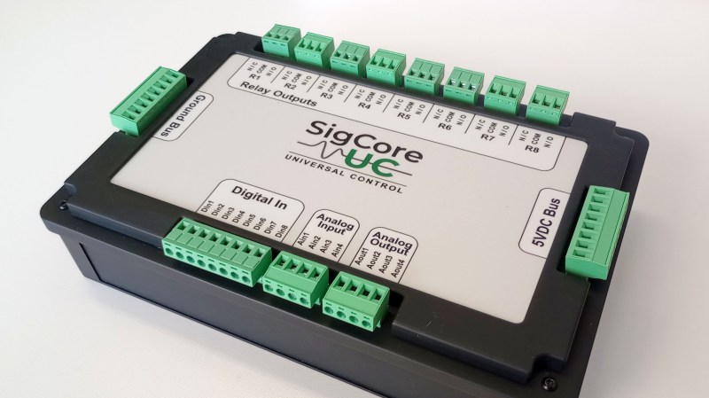
In the video embedded below, [Edward] runs us through some of the features which he explains are a complete industrial control and data collection system. Features include Ethernet, WiFi, and Modbus TCP connectivity, regulated 5 V bus, eight relays, eight digital inputs, four analog inputs, and four analog outputs. All packaged in rugged housing and ready for installation/deployment.
[Edward] says he wanted something which went beyond development boards and expansion modules that provided a complete and ready-to-deploy solution. If you’re interested in the hardware, firmware, or software, everything is available on the project’s GitHub page. Beyond the Hackaday.io article, the GitHub repo, the YouTube explainer video, there is even an entire website devoted to the project: sigcoreuc.com. Our hats off to [Edward], he really put a lot of polish on this project.
If you’re interested in using the Raspberry Pi for input/output you might also like to read about Raspberry Pi Pico Makes For Expeditious Input Device and Smart Power Strip Revived With Raspberry Pi.


Having the ground pins so far away from the analog/digital IO pins seems like a weird design choice.
Yeah, that is an odd design choice, I’d definitely want to have analogue pins interleaved with grounds and at least one ground on each digital connector.
Critique doesn’t require publishing an alternative. It’s a cool device for sure but there’s nothing wrong with feedback.
I had the same question marks regarding GND and also why only 8x GND for the 16x I/Os. But maybe providing feedback directly via github is more efficient then feeding the trolls here. ;)
sigh not criticising, just commenting and trying to give a tiny bit of advice from my experience of designing automotive diagnostic equipment for a living and the valuable lessons I learned from my mistakes (getting bitten in the backside) when analogue signal integrity was compromised because grounding wasn’t good enough.
But I’ll STFU and not share next time.
Happy?
Yes. No one cares who you are and what you did. If you don’t share your projects on GitHub you are nobody.
Hi CJay,
I do care as many others do so please do not keep it to yourself. That’s the added value of this comments section.
If some prefer, they can’t choose not to read.
I also think the context you added later may have helped better understand this as what it is.
So its not allowed to discuss weird design choices anymore? With that logic we also should not be allowed to criticize car manufacturers unless we build our own right?
Sir, if you just want to provoke: Reddit is the other way. You will be much happier there.
Besides the analog signal-to-GND spliting also only 8x GND for 16x I/O could become inconvinient.
But “nobody” should provide feedback to the developer via hackaday comments – github is the better channel imho. ;)
Very nice job!
Great design job.
Is the hardware available for purchase
?
Stanley
Where can I buy this!!?
SigCore UC is currently in the pre-launch phase on Crowd Supply. You can follow the project and subscribe for updates and launch notifications here:
https://www.crowdsupply.com/en-z-em/sigcore-uc
Hardware availability and timing will be announced through the Crowd Supply page.
I’m interested as heck and I don’t really have a clue what it does.
Having just reverse-engineered a non-HVAC-engineer’s implementation of a complex HVAC solution, I couldn’t help but notice some similarities between that and a relay module for a multi-zone heat pump installation, For example, the IntelliZone2 relay board.
That’s a fair comparison at the wiring and I/O level. Where SigCore UC diverges is scope and intent. It’s designed as an industrial-grade control platform, not a fixed-function or project-specific controller.
In addition to relay and I/O handling, it supports database-backed logging, industrial PID control, universal analog and digital I/O, and flexible analog outputs. It can be applied to HVAC control, but the design is intentionally broader and more precise than a single-purpose implementation.
I couldn’t view a schematic, to contribute my thoughts. No pdf for it.
https://hackaday.io/project/203656/files has no “download” button, only a “preview” of an old sch file.
No I’m not loading up KiCad to do this lol.
I think boards like this need a watchdog in case the Pi hangs. I’m presently working with HVAC logging and need isoalted DI’s.
A better explanation of the project would help. Where does the 5V come from lol
The schematic is available in the repository here:
https://github.com/edwardschmitz/sigcore-uc/blob/main/docs/Drawings/SCH_Schematic1_2025-09-26.pdf
A hardware watchdog is planned for the release version
I don’t know what all the goals of this project are. The box has very nice build quality, and as a platform for interacting with physical hardware with C# and Python, it looks like it’s very nice. But several things are not what I would expect for a controller designed for automation, at least not industrial automation.
As far as I can see, the box is not DIN rail mountable.
The “bus” voltage is 5V, not 24V.
The analog outputs only go from 0-5V not 0-10V.
There’s a external 5VDC switching supply that comes with the device
I initially thought the picture showed an e-ink screen where the printed insert is, and wouldn’t that be cool for prototyping?! You could update your labels in software.
That would be cool and I’ve definitely thought about that. It’s certainly possible