If you’ve seen a big air-variable capacitor, you may have noticed that some of the plates may have slots cut into them. Why? [Mr Carlson] has the answer in the video below. The short answer: you can bend the tabs formed by the slots to increase or decrease the capacitance by tiny amounts for the purpose of tuning.
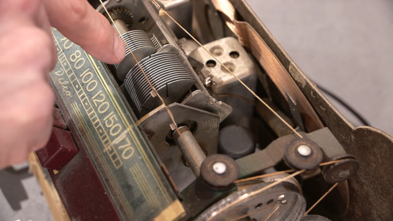
For example, if you have a radio receiver with a dial, you can adjust the capacitor to make certain spots on the dial have an exact frequency. Obviously, you can only adjust in bands depending on how many slots are in the capacitor. Sometimes the adjustments aren’t setting the oscillator’s frequency. For example, the Delco radio he shows uses the capacitor to peak the tuning at the specified frequency.
You usually only find the slots on the end plates and, as you can see in the video, not all capacitors have the slots. Of course, bending the plates with or without slots will make things change. Just don’t bend enough to short to an adjacent plate or the fixed plates when the capacitor meshes.
Of course, not all variable capacitors have this same design. We’ve seen a lot of strange set ups.


It is nice to see videos like this.
Part of the (nearly) lost skillset tools, and techniques. .
Mr Carlson makes it look easy.
I have done this as part of the rebuild and alignment of the TRW built Heathkit LMO modules (a 5.5-5.0MHZ VFO. I built a test jig with an external power supply and a spare dial assembly for Heath SB series gear. After getting the end points established, frequency error is recorded every 50KHZ. Now you have the first set of numbers from which you will begin blade tracking, in for lower, out for higher. To get down to less than 200HZ error over 500KHZ takes several tries. This was an after school project when I was a senior in high school (1974) It took 8 days working an hour a day. When I finished for the day the LMO was covered in shop rags completely and left powered on until the project was finished.
Thanks HAD for the memories…..
I agree, great memories! When I was in high school in the 80s I too spent hours and hours tuning and fixing tube ham equipment with variable air caps. I could never afford anything new so I would often see the previous owner’s attempts to bend the plates which is how I realized what the slots were for! (I was lucky to get 200Hz error, mostly I just stayed a few kHZ away from band edges.)
As a person not knowing much but enjoying your video presentation, I would like to ask a childlike possible solution to the problem. Since the dial pointer was off alignment by about an eighth of an inch, could you have adjusted the string loop of the pointer to mechanically correct the alignment? I understand such a solution would defeat the point of the electronic lesson. But is it a solution?
Isn’t the problem that the rotation of the axis/le of the capacitor plates isn’t granular enough, the bending of flaps stakes out a range of capacitance there4 frequency?
Actually no….
The change in capacitance does not correlate to a linear change in frequency.
To blade track a variable with a degree of precision it takes several passes between the low end point adjustment (usually a variable inductor.) the high end point adjustment (usually a padder trimmer cap attacked to the variable, and one or more of the edge blades on the variable…
On a production line, you will only be allowed anough time to set the low end, high end, and center….
Did I say linear? I didn’t say linear. Is linear important in this context? Why are you saying linear?
The video said it was accurate at the ends of the scale so adjusting the pointer would make it accurate in the middle of the scale but no longer accurate at the ends.
Are these capacitors still being manufactured? I find them extremely difficult to find ay more and very expensive.
Oren Elliott Products (OEP). “New old stock” suppliers like Surplus Sales of Nebraska. Restoration suppliers like Ken’s Electronics (Michigan) and Mike’s Electronic Parts (Ohio).
Yes, but they are not used in consumer electronics anymore. Many of them are made to order.
You can find usually find used variable capacitors from radio receivers at a ham fest for a reasonable price. Look for someone that has junk boxes full of salvaged components.
If you need a high voltage capacitor for a mag loop or antenna tuner, there are some designs online that you can build yourself. Look for the butterfly style capacitors, they don’t have an electrical connection to the moving plates so they handle high current a lot better. There are lots of companies that will laser cut the plates for you. The rest of it can be made with parts from the hardware store.