Over the decades we have seen many DIY clocks and wrist watches presented, but few are as likely to get you either drawing in the crowds, or quietly snickered at behind your back, as a binary watch of some description does. A wrist watch like [qewer]’s qron0b project which also uses BCD encoding to display the current time is among our more rare project types here, with us having to go all the way back to 2018 for a similar project as well as a BCD desk clock.
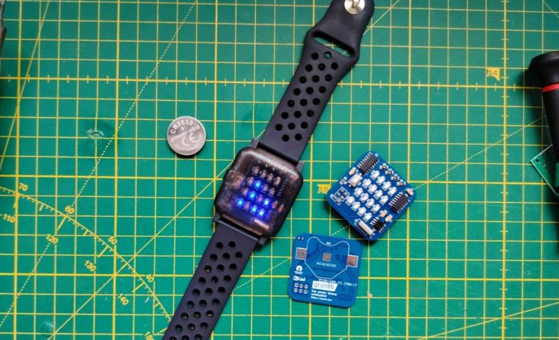
As is typical, a single CR2032 coin cell powers the entire PCB, with an ATtiny24A or compatible as the MCU, a DS1302 RTC and the requisite 4×4 LED matrix to display the hours and minutes. Technically three LEDs are unneeded here, but it looks nicely symmetrical this way, and the extra LEDs can be used for other tasks as the firmware is expanded from the current setting and reading of the time.
The AVR C firmware can be found in the above linked GitHub repository, along with the KiCad PCB project and FreeCAD design files for the watch body. The body accepts a 22 mm GT2/GT3-style watch strap to complete the assembly. With a single CR2032 you’re assured of at least a few months of runtime.


Here’s another BCD watch, although battery life is way worse at around a week:
https://jonathan.rico.live/projects/m-watch/
Super cool project, great work! I also once built an LED watch but it only lasted about a week, I’ll look into the project to learn how he got the battery to go so long.
Code written with
delay_ms()everywhere 🤦♂️Hope your carrying an entire pack of those CR2032 cells.
how would you do it better?
You put yourself to sleep, with an interrupt to wake you up later. If you have nothing to do then you might as well do literally nothing.
Hey! Project creator here.
In the firmware, for main timekeeping tasks while the watch is awake, a global “uptime” variable that gets updated from the TIM2 ISR (TIM2 is configured to tick every 1ms) is used. delay_ms and delay_us are used mainly for either simple animations or communication delays. The watch uses around 1mA in awake mode (in sleep it’s around 30uA), it wakes up only when you press the button and sleeps 10 seconds later. With those calculations and my own usage experience, it should last around at least 7-8 months from a single CR2032 cell.
LMFAO WHAT???? AND WHO ARE YOU??? is that the reaction you give to hard facts???garbage low-effort ragebait lmao, or you’re just jealous, which in that case I’ll take it as a compliment :D
For starters, I am not a narcissist high on my own farts, desperately trying to attract HR attention in the age of IT graduates oversupply. That should be enough, if you want more though, go ahead and try to find more about me.
Also, you’re not even a beekeeper.
This is a terrible design for those reasons:
Blue LEDs are a terrible match for a CR2032 coin cell. The cell voltage will quickly drop beyond the useful range to light the LEDs.
the spaghetti code with delay loops is terribly inefficient. Gosh. there are efficient libraries using timers around.
DS1307 , a 80s era RTC chip uses something like 1200x more current for keeping time than for example PCF8563, and has twice more drift.
the shift register is useless: 5 pins are enough to charlieplex the 4×4 matrix, and would use less energy, since that chip is ALWAYS enabled (/OE tied to ground)
And the schematic… oh no, please. what´s the point to butcher it in 4 parts for such a simple circuit ?
and what´s this PWR_FLAG label that is connected both on the power rail and the ground ?
“With a single CR2032 you’re assured of at least a few months of runtime” gratuitous, very unlikely, unverified HaD-style assumption.
Hey! Project creator here.
Thanks for the feedback. It’s quite literally my first ever time designing anything low-power (and as mentioned in the Github README) there are a few small design issues. But to address your points:
Blue LEDs are just for aesthetic reasons, they can be replaced with green or red. The cell voltage does NOT drop “beyond the useful range” since the watch uses 1.5mA max while awake. A CR2032 can easily supply that for a short period (the watch is awake for 10 seconds typically).
My code already uses timers, delays are used mainly for either simple animations or communication delays. Could definitely have some improvements there but if you actually read the code, you’ll see it’s far from spaghetti.
I used a DS1302 for ease-of-access but yeah a PCF8563 would definitely be a better choice. Same with the shift register, it’s not strictly needed. They can definitely be improved, as I said, this is my first time designing anything low-power and I’m a student.
A PWR_FLAG label is a KiCAD specific thing to avoid ERC errors. Basically it tells KiCAD that those power nets are driven externally.
Power usage is NOT a mere “assumption”. The watch uses around 1mA (+- 0.5 depending on what it’s doing and how many LEDs are on) while awake and around 30uA in sleep. If you do the math, with a CR2032’s 250mAH capacity, you get around 11 months (and if we include the awake times, you’ll still get 6+ months easily). It’s been going strong for more than a month since I’ve made it and the battery has barely depleted, closely matching the calculations.
I think that criticism is not entirely valid.
Yes, red LEDs would be more suitable for low voltage applications but with the flat dicharge curve of a 2032 cell, you are probably fine until the battery is almost depleted.
The DS1302 should draw less than 1 uA, which has little impact on the battery life.
And what is supposed to be wrong with the schematic? I find this kind of segemented schematic much more readable than having to follow traces across the entire page. This one is completely OK.
There is always stuff you can improve on, but especially for a beginner’s hobby project, this is really well made!
I almost want to see more complaints with even less detail; I’m not used to insulted authors responding so calmly and maturely, and I am not certain I could do it.
Yeah, right? Super jerky comments from Iman, but it’s still very nice to hear the design rationale.
@Iman. Be nice.
Although I technically agree with the points mentioned… keep in mind that we’ve all got to start somewhere. For a hobby project, all that matters is that it works… or at least “works for a while”. And than carry on to the next project. It’s not that these things will be sold by the thousands or that you are forced to build one yourself, so who cares?
You’d be surprised how wide the actual range can be for LEDs. Especially if running at lower than nominal current cause while we tend to treat diodes like having a fixed forward voltage: It actually changes quite a bit based on the current.
And yeah. Considering how bright these little fellas can get nowadays at nominal current, we often do drive them at <1mA. At which a bright blue led can have a voltage of ~2.5V.
The datasheets state that DS1302 uses 1.5x current of PCF8563, so I don’t know where your 1200x comes from. And since you’re suggesting that a few months of runtime is very unlikely, why would anyone care about a few seconds of drift? Kind of a moot point.
I would argue that they aren’t rare so much as that they had gone out of style for a while. Like they used to be widely sold as geeky gadget clocks during the early 2010s, lots of instructables around and my first few projects were binary clocks including a regular made with 4024 chips on a perf-board and a BCD pocket-watch with an ATMega on the first PCB i had made at a batch-pcb fab.
But then they just went… poof. Gone. Maybe there was “binary-fatigue” or something, but just no peep or attention for a long time.
Still. Nice work. some things could definitely benefit from some iteration as the power-draw could be vastly reduced, but when is that not the case? Either way a good reminder to finish the re-designs of my old binary clocks.
A 4×4 display can show time in cistercian mode :)
https://cdn.hackaday.io/images/12611739712295503.png
https://hackaday.io/project/202436-cis-4