Variable capacitors may be useful, but the air gap that provides their capacitance is their greatest weakness. Rather than deal with the poor dielectric properties of air, some high-end variable capacitors replace it with a vacuum, which presents some obvious mechanical difficulties, but does give the resulting capacitor a remarkable quality factor, high-voltage performance, and higher capacitance for plate area than their air-gapped brethren. [Shahriar] of [The Signal Path] managed to acquire a pair of these and took a detailed look at their construction and performance in a recent video.
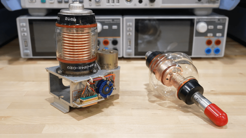
The vacuum capacitors don’t use quite the same parallel plate design as other variable capacitors. They instead make the plates out of interlaced concentric metal rings mounted in a vacuum tube. Both sets of rings are connected to terminals, one fixed and one capable of being pulled in or out on a threaded rod surrounded by an accordion-pleated copper seal. A nut on the outside pulls the rod out, and the interior vacuum pulls it in toward the other set of plates. Unfortunately, since the mobile terminal needs to be mechanically connected to some adjustment mechanism (such as someone’s hand), it can’t really be at a floating voltage. The mobile terminal needs to be grounded for safety. Alternatively, for automatic control, one of the capacitors had a chassis with a motor, gearing, and a positional encoder.
[Shahriar] also tested the capacitors with an impedance analyzer and lock-in amplifier. They had fairly low capacitance (for the one he tested, 36 pF at maximum and 16 pF at minimum), but the dissipation factor was so low and the DC impedance so high that they couldn’t be meaningfully measured. He also tested one at 5000 volts and found almost no dissipation.
We recently saw another video going over a lesser-known feature of normal air-gap variable capacitors and another new non-standard variable capacitor design. On the opposite end of the fanciness spectrum might be this variable capacitor built out of aluminium cans.


What about a stepper motor enclosed in the glass?
What about it? What is the perceived problem that a stepper is a solution to?
I’m guessing leakage through the seal, and the need for the variable terminal to be grounded because it’s mechanically connected to something (though I’d guess that can be overcome with a rubber belt to drive it?).
If those aren’t issues, then would be interesting to know! My experience with vacuum tubes is limited to completely sealed ones.
The seal on these capacitors is completely static: it’s a normal metal-glass joint at the stationary end of the bellows. It doesn’t move.
Bad idea; over time the motor will contaminate the vacuum.
Do you think that would be for an intrinsic reason, or just because all of the steppers you know have some sort of grease-packed bearing?
Organics like Epoxy outgass under a vacuum.
Are you really going to build a stepper motor out of non-organic parts just to have it live in a vacuum?
Not cost effective.
This was tried in the forties and fifties and was reliable. back then they used an induction motor, and it still wasn’t clean enough.
Funny, I have a motor that runs at 3000 rpm in a high vacuum. It’s 40 years old and still works great. Silver is the lubricant, I’m told.
Note it’s an induction motor: The armature is just a chunk of metal. The stator windings and their out-gassing insulation are outside the glass envelope.
Must be a TM pump.
I know about those…….
They are different, the vacuum is Not Static like a sealed bottle.
Remember these vacuum variables don’t have Ion Pumps.
There are nearly always virtual leaks of one magnitude or another.
It’s a rotating anode xray tube. It’s a pretty hard vacuum.
Could go much simpler: a magnet inside the glass, and another outside the glass with a knob attached to it.
putting the motorised mechanism in the vacuum envelope makes sense technically as static electrical feedthroughs would be more robust and reliable however that would need offsetting against the cost of the tube itself – would be more or less cost effective or would it enhance saleability of mass produced device? I’d suggest that engineers would have already performed a cost-benefit analysis. perhaps there are variants of this type of tube where the mechanism was enclosed.
So what do you do about wear?
Wear creates particals and partials under an electrical field become destructive ions.
If your getter doesn’t clean it up and keep it clean enough, you turn up the voltage and drive the ions into the tube walls. In a thermionic tube you can’t drive them into the cathode because they will promptly evaporate right back out again.
The ion crud will evaporate back into the vacuum over time, so you have to repeat that conditioning process from time to time. At some point the arcs come back faster than you can tolerate, so you scrap the device.
Vac variables have been in use for decades. There is no improvement necessary.
Their use isnt so much for higher voltage than for higher rf current. When you get to hundreds to millions of watts of rf a typical air spaced cap just won’t work.
I have probably a dozen or more vac variables in use here at my station either in tuning networks or high power amplifiers.
What would happen if you replaced the vacuum with a highly insulating gas like sulphur hexafluoride? They use that in high-voltage switches to prevent arcing.
Low D..
The best caps have nothing between their plates.
Why not put one of the plates outside the glass?
Putting one of the plates outside the glass means that the glass becomes part of a dielectric sandwich. The flaws of the glass as a dielectric become a part of the flaws of the finished product.
It’s not a terrible idea, it’s just that there are different tradeoffs involved.
See Leyden jar.
How to ensure that capacitor is still vacuumized properly? Here is no getter?