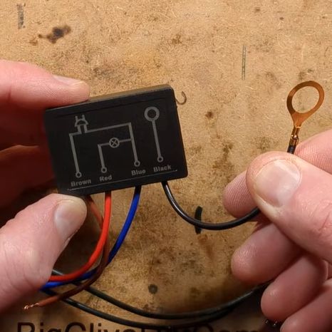
 In [Big Clive]’s recent grab bag of tat ordered from Chinese commerce platforms, there were two touch light control boxes that can turn any ungrounded conductive surface into a mains load dimmer control. Of course, the primary reason for the purchase was a teardown, and a teardown we got.
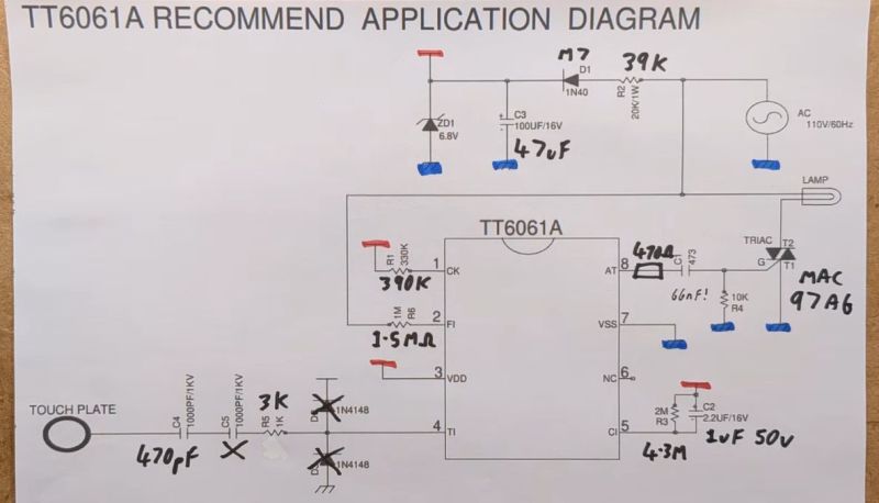
These unassuming little boxes are built around the Tontek TT6061A, listed as a ‘touch dimmer’, which uses a triac to control the output current. There are four levels, ranging from off to full brightness, before the next touch event turns the output off again.
With the output off, [Clive] measured 0.7 W power usage. After popping open the plastic enclosure, the circuitry turned out to largely follow the recommended application circuit from the datasheet — as can be seen in the above screenshot — with apparently a few cost optimizations, in the form of omitted diodes and a capacitor.
The problem with these devices is that they are only really suitable for dimming low-power resistive loads like incandescent lights, with LED lights likely requiring the unpopulated capacitor spot on the PCB to be populated to tweak the chip’s triac timing, among other changes. There are also the slight issues with no real concern with them radiating EMI, and the exciting possibility of getting shocked at mains voltage without at least a class-Y capacitor installed.
Perhaps using a capacitive touch controller instead that works through plastic, for example, isn’t such a crazy alternative here, especially since they’re not really much more expensive and less likely to shock you. Want to create your own triac designs? We have just the post to get you started.


It’s ironic that something made in China even needs “cost optimizations” by omitting just three components. I also noted several electrolytic capacitors were reduced in value as well.
I reverse engineered a WiFi light switch that tried to set itself on fire a few years back. It was one of the ones that requires no neutral, so the design was interesting to me.
They followed the controller IC manufacture spec except for one thing. They replaced a tiny diode with a 0 ohm resistor, presumably to try and get costs down.
Apparently that diode was more than a recommendation from the manufacturer, as without it, the controller can fail and cause the IC to conduct AC through it. It doesn’t fail immediately, so they probably “tested” their “optimisation” and thought it good enough.
Don’t stick random Chinese tat in your walls!
I don’t know much about mains-powered electronics nor capacitor classes, but I wouldn’t call using a single 3kV-rated 470pF instead of two 1kV-rated 1000pF in series an omission. It wouldn’t be the first time in human history when the reference design is suboptimal.
It is quite common (for safety reasons) to have 2 components in series. If one fails (short) there there is still an extra barrier between mains and the human body.
Use a hot dog as a touch-controlled light dimmer. Securely attach one lead to an end of the wiener. The other lead gets attached a band on your wrist. Now, as you stroke the frank the impedance changes and varies the brightness of the lamp that is connected in series with this device and the mains supply. This could also be adapted to adjust the period of a 555 timer, for controlling other devices.
Not sure that “stroke the frank” is the kind of statement most of us readers are accustomed to here on the HAD forum…