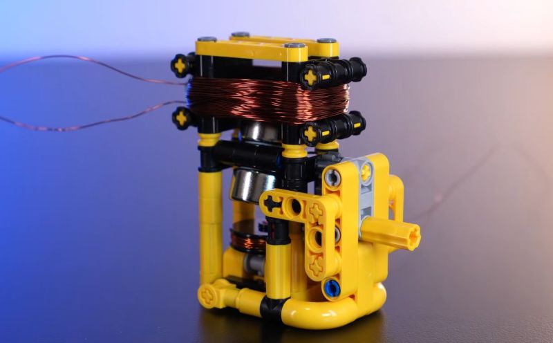
Although [Jamie’s Brick Jams] has made many far more complicated motor design in the past, it’s nice to go back to the basics and make a motor that uses as few parts as possible. This particular design starts off with a driver coil and a magnetic rotor that uses two neodymium magnets. By balancing these magnets on both sides of an axis just right it should spin smoothly.
First this driver coil is energized with a 9 V battery to confirm that it does in fact spin when briefly applying power, though this means that you need to constantly apply pulses of power to make it keep spinning. To this end a second coil is added, which senses when a magnet passes by.
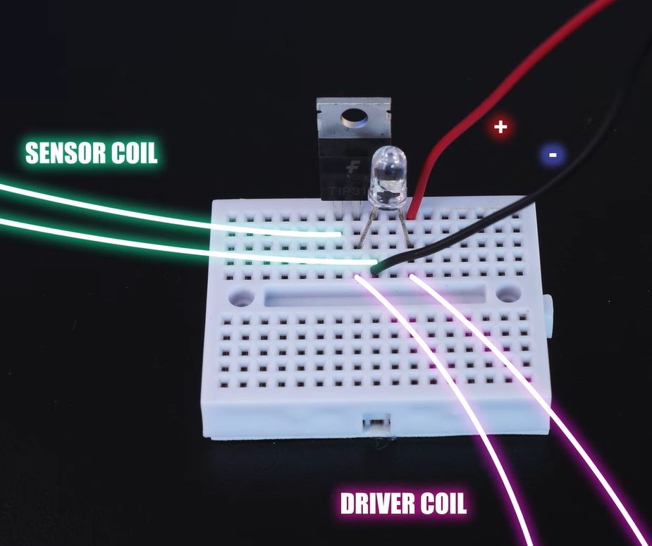
This sense coil is connected to a small circuit containing a TIP31C NPN power transistor and a LED. While the transistor is probably overkill here, it’ll definitely work. The circuit is shown in the image, with the transistor pins from left to right being Base-Collector-Emitter. This means that the sensor coil being triggered by a passing magnet turns the transistor on for a brief moment, which sends a surge of power through the driver coil, thus pushing the rotor in a typical kicker configuration.
Obviously, the polarity matters here, so switching the leads of one of the coils may be needed if it doesn’t want to spin. The LED is technically optional as well, but it provides an indicator of activity. From this basic design a larger LEGO motor is also built that contains many more magnets in a disc along with two circular coils, but even the first version turns out to be more than powerful enough to drive a little car around.


But why? A 3d printer is cheaper than Lego and a 1000 fold, levels up. My son left Lego for Minecraft at 8. He left Minecraft for a 3d printer at 14
Lego is for people who are 38 years young
Cool
Does it deliver any usable torque? If not then it’s not a motor but toy like one of those maneki-neko cats.
Fun fact: Epstein had plenty of those on his island.
You seem to write “toy” like it’s an insult. You do realize that it’s built with LEGO bricks, right? I’m pretty sure “toy” is well within the pedagogy-envelope for this project :)
Weirdly aggro about legos, my man.
I assumed that the LED is there to prevent induced voltage spikes from frying the transistor?
Could be but it’s not efficient and LED can burn out from repeated spikes. Regular diode across the motor coil is preferable to LED.
Is there anything which could be done to this topology of motor to 1) make it self-starting and 2) let you control the direction it actually turns in when it self-starts? Because whilst I suspect it is much less efficient than 3 phase BLDCs, it nonetheless looks like it could be useful in places where you’d rather not have any brushes than eventually wear down, nothing in this design looks like it will wear away with use. And unlike a BLDC the control circuit can be so much smaller and cheaper, for the kind of applications where you’d like the motor to last “forever” but don’t need the ful complexity of a proper 3 phase drive. Thanks
Imma let you finish, but the greatest simple motor project of all time was in Life Magazine and used… paperclips.
https://www.rfcafe.com/references/life/images/electric-motors-life-december-27-1943-9.jpg
Good, but the homopolar motor is simpler.
https://en.wikipedia.org/wiki/Homopolar_motor
FYI, I was replying to ken
Not even close imo.
A single cell (AA, C, D), a solid copper wire (even a paper clip) and a diametric magnet is quite a bit simpler imo.