
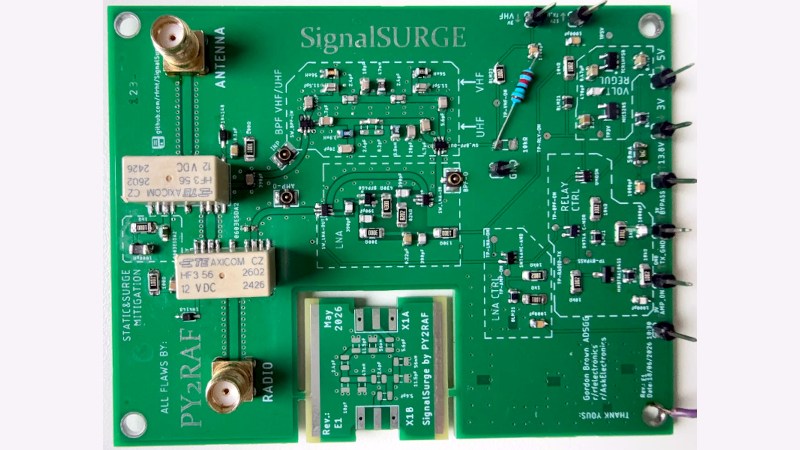
It’s an unfortunate side effect of proximity to a large transmitter that the received signal can overload a receiver’s front end even when tuned to other frequencies. [Rfrht]’s had this problem with nearby FM broadcast transmissions overloading the 2 metre and 70 centimetre amateur bands. The solution? Design and build a bandpass filter. This allows the signals you want to pass through while rejecting or attenuating out-of-band frequencies. The resulting PCB is very nice indeed.
On board, aside from the filters themselves, are a low-noise preamplifier and relays to switch between receive and transmit. Everything is controlled by logic-level signals. All components are surface-mount, and the PCB layout clearly takes special care with RF routing.
We can honestly say there have been times in the past when we could have used this project. Unfortunately, our filters, built Manhattan-style, weren’t anywhere near as elegant as this one. If you want a filter and can’t build this project, consider a filter prototyping board.












I like the indication of the filters on the board itself. The cutout in the middle is interesting, though. “All flaws by…” is hilarious.
The silk screening is impressive, no doubt helpful when coming back a decade or two later, perhaps the next owner will appreciate it.
Having miniature connectors, presumably for testing purposes? seems like a good Idea, no doubt the extra cost is more than made up for by making the solid probe connections easier. It’s always nice to find humourous little additions to PCB artwork, but it’s especially nice to find a PCB where everything’s labeled so thoroughly.
A simple helical filter can do the same job at about 1% of the cost and complexity
Agreed;
VHF and UHF are very easy places to make filters that work well.
It’s almost like plumbing.
Back in the 60s I was responsible for running 30 and 50 MHz Riometers (Relative Ionospheric Opacity Meter) at McMurdo Sound, Antarctica and at Shepherds Bay, N.W.T. Canada, for Douglas Aircraft’s Space Sciences Department. Our cosmic radio noise signal was about 1 microvolt at 30 MHz and less at 50 MHz. A solar cosmic ray event could drop those as much as 20 db or more. That’s what we wanted to measure. The receivers were radio astronomy type receivers with an RF switch at the front that switched between the antenna and a vacuum tube noise diode at 340 Hz. That signal was amplified by a conventional receiver and then then detected with a phase sensitive detector, integrated and then fed back to the noise diode filaments to raise or lower the noise output to match the antenna input. The plate current was what we recorded. The nearby Navy transmitters that were transmitting 10s of kilowatts sometimes interfered with our signals. Usually that meant they needed retuned to get rid of spurs. In the meantime our recordings got messed up.
After much thought and perusing what filters were available at those frequencies I bought two beautiful helical filters for about $300 each and replaced our woven shielded coax with flexible, but solid, aluminum covered coax. Problem solved! The Arctic receivers didn’t have any interference problems, but I put the same filters and coax on them just so they were identical.
There are quite a few ham band filters out there.
Add a preamp, and that’s much less common.
Bypass protection for 50w transmit – scarcer again, and something plenty of hams would appreciate.
Nothing “pulls in” a signaln especially a BPF..
“pull in signals” is hamradio slang