We’ve covered dozens of projects about getting images of Earth’s weather straight from the source. It’s not too much of a trick to download images straight from our constellation of weather satellites, but what about space weather? We’ve got satellites for that too, of course, but to get a good look at the Sun, they’re out of reach of most homebrew ground stations.
That’s about to change, though, as STEREO-A returns to our neighborhood after a 17-year absence, making citizen science a reasonable proposition. The STEREO mission — Solar Terrestrial Relations Observatory — was launched in 2006 with a pair of satellites in heliocentric orbits. STEREO-B was lost in 2014 due to a navigational glitch, but STEREO-A has spent a lot of the intervening years watching the backside of the Sun relative to the Earth. As [Scott Tilley] explains, the satellite is now approaching inferior conjunction, where it will pass between the Earth and the Sun.
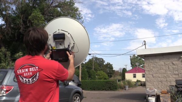
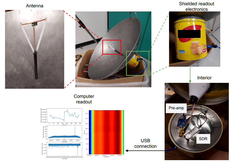
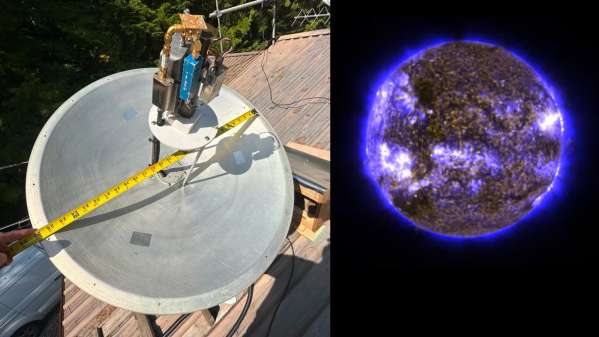
This close pass makes STEREO-A’s X-band deep-space beacon readily available to hobbyist-scale equipment, like [Scott]’s 66-cm dish antenna. The dish is mounted on an alt-az telescope mount for tracking, and sports a host of gear at the focus, like LNAs, filters, mixers, and an Ettus B200 SDR. It’s not a cheap setup, but compared to what’s usually needed to listen to STEREO-A, it’s a bargain. The process of demodulating and decoding the signals was a bit more involved, though, requiring not only SatDump and some custom code but also a lot of patience. The images are worth the wait, though; [Scott] shares some amazing shots of our increasingly active Sun as well as animations of recent sunspot activity.
If you’re interested in getting in on the STEREO-A action, you’d better get hopping — the satellite will only be in the neighborhood for a few more months before heading off for another pass around the back of the Sun.