
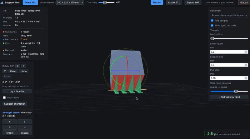
Perhaps one of the most contentious issues in 3D printing is that of supports, both because they’re an uncomfortable reminder of how gravity affects our prints and because the very idea of there being ‘one right way’ is bound to get you into some spirited discussions. That said, [Matthew Trahan] figured that neither regular grid supports nor organic tree supports are the answer here, and that the better answer is found in fins.
The problem with existing support approaches especially with FDM prints is that they can be fairly wasteful in terms of material, and they can leave serious marks on the printed object’s surface that require post-processing. These fins on the other hand are designed to require as little material as possible and snap off as cleanly as possible. The tool, developed with the assistance of Claude, can either run locally or be accessed via printfins.com.
Currently the idea is that these fins are baked directly into the STL model so that it’s a one-time thing, but it may eventually become available as a slicer plugin. The basic concept was pitched by [Slant3D], who gets credited in the video below, although in their approach they used CAD software to add the fin supports manually.
The fins are there to provide the support base, while small tines can be added to reinforce the connection to the model. These do make it less easy to snap off with minimal scarring, of course. Conceivably these fins could be made even more light-weight by adding gaps, but that probably would add to the print time.












if he’d just rotate that cube til its flat, he wouldn’t need supports
haha but really that’s how i do it. sometimes it’s a struggle to design support into the object itself but i’ve never had to use support about 140 projects. knock on wood.
If your cube is decorative, then the orientation of layers is not important. But like CNC Kitchen 3D Slant (both mentioned in the video) and others showed, the object is strongest if layer lines are diagonal to the use of the object – thus printing at 45 degrees angle.
I’ve seen it long ago on both channels Matthew referenced and I’ve done thia a dozen time but always struggled to add the fins to the print for maximum strength. I’m glad someone automated it..
haha i’m not gonna say you’re wrong but if the difference between ‘strong enough’ and ‘not strong enough’ is layer line orientation then it’s not really strong enough. there is a difference but with PLA or PETG at least, it’s less than twice.
i’m saying this because i think it’s a great example of meditating on the wrong thing. printability is a huge and continuing challenge that you must always confront. getting something 1.5x as much strength per mm^2 of object by worrying about layer line orientation is absolutely optional. you can leave that step out entirely and it doesn’t affect you at all.
the thing is, if your object is only 1.5x as strong as it should be, and orientation-maxxing is enough to get it to ‘work’, that’s one of the many many signs that you should be using a different material / methodology instead (metal, wood, vitamins, etc)
As a counter to this point, if your object gains 50% strength and you already included a safety margin of 200%, your object now has 300% safety margin.
Also, its not always about strength: orientation can also be used to influence likely initial failure behaviours.
For example in a hand held tool maybe a clean shear off is safer than a crack propagating into the gripped area, or maybe the crack is safer since it prevents the hand slipping into a danger zone.
I overthink these things all the time when printing for toddler age relatives, since if never forgive myself if something I made injured them seriously. I’m often slightly appalled at printables toys with pointy bits and concerning potential failure modes. Maybe I’m biased cause I remember falling face first into a pencil pot at school and getting impaled through the cheek by a HB pencil, but it’s better safe than sorry IMO.
a handheld tool that sees considerable loads and will become unsafe if it breaks is a perfect example of what i’m talking about: no no no no don’t 3d print it
This is a lot more complicated of a topic than can be expressed by “just print at a 45” because it really depends on which direction the load is going to be carried.
If you have hardware which is going to put forces in a direction where layer lines are going to break it through normal use then one should probably reorient or change the design so that the load is carried on a different face.
Not knocking the work of others in testing…but Slant 3d has a very clear reason to make it seem that this is the best…and it is purely marketing for their printer.
Most who have printed quite a bit know very well how to design for 3d printing.
Also, when using materials like PETG I have found they are just as likely to break in any direction if they are going to break along a layer line. ABS and PLA…not so much…they do break on the lines quite often.
All that aside. I don’t personally use tree supports. Most of the time I just use rectilinear since it often does better with curves and rounded objects. Especially if you tune the interface layers correctly.
Totally agree on your take of slant3d. They have some brilliant perspectives and short form educational insights into print strength and design considerations. I often use them for apprentice training material.
However their videos are often marred by their bias towards only considering their own printers, and failing to disclose/disclaim that fact.
I don’t think there is any undisclosed bias in the Slant3D videos. At least in the ones I’ve seen (which include the ones on rotated printing and the fin supports), the presenter is very up-front in saying that many of the design approaches are meant to increase the printability of objects without relying on specific slicer features. This is very important when submitting jobs out to printing services such as theirs. They don’t sell printers or software, they offer a printing service and they are very up-front in saying that they are offering advice to make it easier to create a design that can be reliably printed without the specific slicer settings used during development.
The advice that applies to designing for their service applies to any design that is meant to be shared.
Exactly, this has been known for years, especially in the 3d2a community. It’s always weird to see these “discoveries” that people in the know have already been doing for a long time.
There’s an XKCD for that…
Did anyboy think of putting the bed at an angle ?
I don’t think that was the point – but rather was the demonstration. I’ve been doing this same thing for internal supporting of an overhang for a power-supply cover. I didn’t want a whole lot of supports so I put in these same things (been doing it for quite a while) that are breakaway. It’s just a demo. Mine is a full overhang – and I do it because I want the strength in that orientation.
if you use automatic support painting under the support painting tool in PrusaSlicer you end up with much sparser support coverage.
It wouldn’t be faster, obviously, but if it would work for resin printers, it would save quite a bit of resin, and possibly reduce the chance of the support pulling the part off the bed. Some experiments are in order…
Perhaps a way to have stronger prints?
https://phys.org/news/2026-09-liquid-crystal-page-steel-phase.html
3D print trees can be used as spacecraft greebles
Hm, I’ve done those types of support for my models destined for my SLA printer a number of times. Wedges and cones are both useful.
Baobab supports in preflight slicer are a good best of both.
Have a liste of small pieces to print and use them as supports
I recently ran across this video from clough42 about making a fin support even cleaner to remove:
https://www.youtube.com/watch?v=1Zocl7n98xY
“Without a Trace: 3D Printed Supports That Remove Like Magic”
It involves modelling the support as a separate object and telling the slicer to treat the object slice each independent object (Not sure which slicers can do this, I’m trying with orcaslicer and it seems to work). Once sliced, the two objects touch but are printed as separate tool passes, so they should not be as fully bound as if tines were involved.
Since printfins.com makes the fins after the fact, it probably does the same thing.
Coincidentally, I just finished a design and slice for this approach last night (won’t get to trying the print until tonight) for a DeWALT battery cover. I’ll see how it prints, then try running it through printfins.com.
Depending on the printer (mostly on how smooth the x/y motion is), you can also just move the fins one or two layer’s-height – or else one nozzle-width, whichever is greater – away from the model and have it print correctly. (Needing to import it into a CAD software, of course, but not really needing anything more capable than TinkerCAD.)
My most extreme example is when I was having trouble printing a custom Raspberry Pi case for a project (which had to be printed standing on one edge to eliminate stringing problems and keep the ports at the correct size), and ended up attaching one edge to a 0.2 mm thick raft that was also attached to fins designed to be 0.4 mm away from the model. (I was using a 0.2mm layer height for the print.)
No stringing, and the model didn’t fall over (as it did consistently without the fins), but that was on someone else’s Bambulab printer. I would likely need to make the fins touch the model if I did it on my old Creality (though I’d rather just drop the print speed and keep the gap).
I realized I’d never followed up with results.
The “clean removable support” method seemed to work very well, there were slight indentations where the two objects met, but they were smooth.
Loaded the same base object into printfins.com site and let it auto-generate supports (with the tines). The result also adhered to the bed during printing and was easy to remove. The bumps from the tines looked small enough that they could probably be almost invisible if I bothered to hit it with a little sandpaper and a heat gun. The site was very well laid out and easy to use.
I didn’t try anything else (like printfins without tines or the clean support method without breaking into multiple objects) because my printer has started globbing with PCTG and I need to get it in tune before trying anything that requires precision.
When designing my own parts, I’ll probably just spend the few extra minutes to add the supports manually in FreeCAD. If printing a file from just an STL or trying to add supports to a complex surface I’ll really consider printfins site.
Forgot to mention enviornment. I’m using an older Ender 3S1Pro with PCTG, so speed was slow compared to modern printers.
What next, frigging lasers? Baby sharkkkk, baby sharkkk, baby sharkkkk, baaabyyy shaaark.