Look around yourself right now and chances are pretty good that you’ll quickly lay eyes on a zipper. Zippers are incredibly commonplace artifacts, a commodity item produced by the mile that we rarely give a second thought to until they break or get stuck. But zippers are a fairly modern convenience, and the story of their invention is one that shows even the best ideas can be delayed by overly complicated designs and lack of a practical method for manufacturing.
Try and Try Again
Ideas for fasteners to replace buttons and laces have been kicking around since the mid-19th century. The first patent for a zipper-like fastener was issued to Elias Howe, inventor of the sewing machine. Though he was no slouch at engineering intricate mechanisms, Howe was never able to make his “Automatic, Continuous Clothing Closure” a workable product, and Howe shifted his inventive energies to other projects.
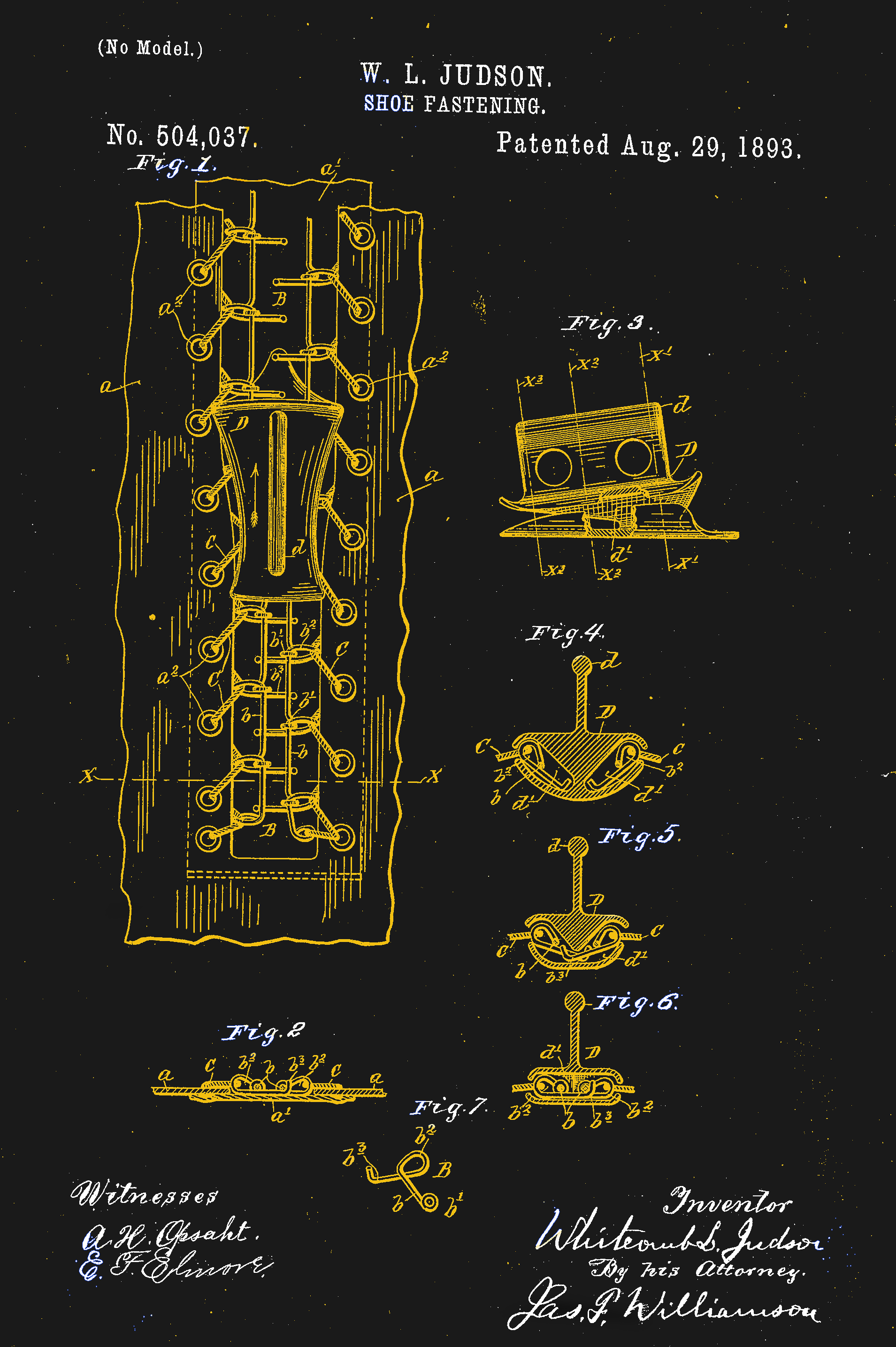
The world would wait another forty years for further development of a hookless fastener, when a Chicago-born inventor of little prior success named Whitcomb Judson began work on a “Clasp Locker or Unlocker.” Intended for the shoe and boot market, Judson’s device has all the recognizable parts of a modern zipper — rows of interlocking teeth with a slide mechanism to mesh and unmesh the two sides. The device was debuted at the Chicago World’s Fair in 1893 and was met with almost no commercial interest.
Judson went through several iterations of designs for his clasp locker, looking for the right combination of ideas that would result in a workable fastener that was easy enough to manufacture profitably. He lined up backers, formed a company, and marketed various versions of his improved products. But everything he tried seemed to have one or more serious drawbacks. When his fasteners were used in shoes, unexpected failure was a mere inconvenience. If a fastener on a lady’s dress opened unexpectedly, it could have been a social catastrophe. Coupled with a price tag that was exorbitantly high to cover the manual labor needed to assemble them, almost every version of Judson’s invention flopped.

It would take another decade, a change of company name, a cross-country move, and the hiring of a bright young engineer before the world would have what we would recognize as the first modern zipper. Judson hired Gideon Sundback in 1901, and by 1913 he was head designer at the Fastener Manufacturing and Machine Company, newly relocated to Meadville, Pennsylvania after a stop in Hoboken, New Jersey. Sundback’s design called for rows of identical teeth with cups on the underside and nibs on the upper, set on fabric tapes. A slide with a Y-shaped channel bent the tapes to open the gap between teeth, allowing the cups to nest on the nibs and mesh the teeth together strongly.
Sundback’s design had significant advantages over any of Judson’s attempts. First, it worked, and it was reliable enough to start quickly making inroads into fashionable apparel beyond its initial marketing toward more utilitarian products like tobacco pouches. Secondly, and perhaps more importantly, Sundback invented machinery that could make hundreds of feet of the fasteners in a day. This gave the invention an economy of scale that none of Judson’s fasteners could ever have achieved.
Putting Some Teeth into It
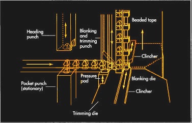
The machinery that Sundback invented to make his “Separable Fastener” has been much improved since the early 1900s, but the current process still looks similar, at least for metal zippers. Stringers, which are the fabric tapes with teeth attached, are formed in a continuous process by a multi-step punching and crimping machine. For metal stringers, a coil of flat metal is fed into a punch and die to form hollow scoops. The strip is then punched again to form a Y-shape around the scoop and cut it free from the web. The legs of the Y straddle the edge of the fabric tape, and a set of dies then crimps the legs to the tape. A modern zipper machine can make stringers at a rate of 2000 teeth per minute.
Plastic zippers are common these days, too, and manufacturing methods vary by zipper style. One method has the fabric tapes squeezed between the halves of a die while teeth are injection molded around the tape to form two parallel stringers. A sprue connected the stringers by the teeth breaks free after molding, and the completed stringers are assembled later.
Zippers have come a long way since Sundback’s first successful design, with manufacturing improvements that have eliminated many of the manual operations once required. Specialized zippers have made it from the depths of the oceans to the surface of the Moon, and chances are pretty good that if we ever get to Mars, one way or another, zippers will go with us.


 In a bicycle, the reciprocating motion of the rider´s legs is converted to rotational motion via a four bar mechanism that is formed by the two leg segments, the bicycle frame, and the crank.