Shake With Your New Robot Hand

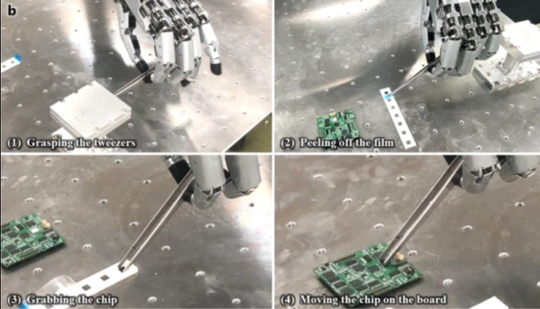
Korean researchers have created a very realistic and capable robot hand that looks very promising. It is strong (34N of grip strength) and reasonably lightweight (1.1 kg), too. There are several videos of the hand in action, of which you can see two of them below including one where the hand uses scissors to cut some paper. You can also read the full paper for details.

Continue reading “Shake With Your New Robot Hand”

Mechanical 7-segment display

A One-Servo Mechanical Seven-Segment Display

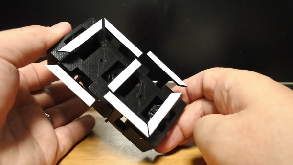
The seven-segment display may be a bit prosaic after all these years, but that doesn’t mean there aren’t ways to spice it up. Coming up with a mechanical version of the typical photon-based display is a popular project, of which we’ve seen plenty of examples over the years. But this seven-segment display is quite a mechanical treat, and a unique way to flip through the digits.

With most mechanical displays, we’re used to seeing the state of each segment changed with some kind of actuator, like a solenoid or servo. [Shinsaku Hiura] decided on a sleeker design using a 3D-printed barrel carrying one cam for each segment. Each hinged segment is attached to an arm that acts as a follower, riding on its cam and flipping on or off in a set pattern. Which digit is displayed depends on the position of the barrel, which is controlled with a single servo and a pair of gears. It trades mechanical complexity for electrical simplicity and overall elegance, and as you can see from the video below, it’s pretty snappy.

We think the best part of this build is figuring out the shape of the cams. We wonder how they compare to the cam profiles in [Greg Zumwalt]’s mechanical display; it uses two separate discs with grooves, but the principle is pretty much the same.

Continue reading “A One-Servo Mechanical Seven-Segment Display”

Linkage Inferring Software Handwaves Away The Hard Stuff

Jokes aside, manually designing linkages that move along specific paths is no easy task. Whether we’re doodling paper sketches or constraining lines in a CAD program, we still need to do the work of actually “imagining” the linkage design. If only there were some sort of tool that would do all that hard imagining work for us! Thankfully, we’re in luck! That’s exactly what researchers [Gen Nishida], [Adrien Bousseau2], and [Daniel G. Aliaga1] at Purdue have done. They’ve designed a software tool that lets us position important bodies in space in particular “key” frames, and then the software simply fills in the linkage for you!

To start the design process, the user inputs a few candidate locations that their solid bodies need to reach in the final linkage path.  From here, these locations get fed to a particle filter. This particle filter seeds thousands of semi-random linkage configurations at small timesteps, selects some of the best-matching ones that most closely approximate the required body locations, removes the lesser-scoring results, re-creates a new set of possible joint configurations based on the best matching ones, and repeats until the tool converges on a linkage that respects our input key frames.

Like a brute force search, this solution takes lots and lots of samples to find a solution, but unlike a brute force search, trials iteratively improve, enabling the software to converge closer and closer to a final solution. Under the hood, the software needs to actually simulate these candidate linkage in order to grade them. It’s in this step that the team wrote in additional checks to remove impossible linkages like self-intersecting joints from this linkage “gene pool” before reseeding them. The result is a tool that does all that trial-and-error scratchwork for you–no brain cycles. For more details, have a peek at their (open access!) paper.

Design software that augments our mechanical design capabilities is a rare gem on these pages, and this one is no exception. If your curious to play with other useful linkages simulating tools, have a go at Linkage Designer. And if you’re in the mood for other tools that fill in the blanks, check out this machine learning algorithm that literally fills in footage between frames in a video feed.

Continue reading “Linkage Inferring Software Handwaves Away The Hard Stuff”

Robot Arms Nudge The Hands Of Time In The Strangest Clock

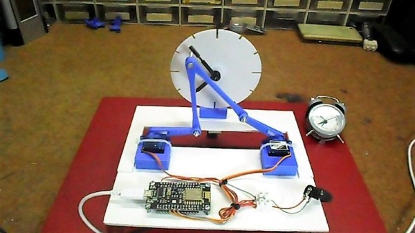
We see a lot of clocks here at Hackaday. Digital clocks, retro clocks, lots of Nixie clocks, binary clocks, and clocks that appear to be designed specifically to be unreadable. But this dual-servo kinematic clock is something we haven’t seen yet, and it’s certainly worth a mention.

[mircemk]’s idea is simple and hearkens back to grammar school days when [Teacher] put a large cardboard clock dial on the blackboard and went through the “big hand, little hand” drill. In this case, the static cardboard clock has been replaced by a 3D-printed dial and hands, while a pair of servos linked together by two arms takes the place of the teacher. The video below shows it in action; the joint in the linkage between the two servos has a screw sticking out that can be maneuvered across the clock face to reposition the hands. It’s a little jittery, though; [mircemk] might want to tune the servo loops up a bit or tighten the linkage joints to make things a little smoother.

Even with the shakes, we find it wonderfully weird and hard to stop watching. It reminds us a bit of this luminous plotting clock from a while back – same linkage, different display.

Continue reading “Robot Arms Nudge The Hands Of Time In The Strangest Clock”

Micro Chainsaw Gets A Much Needed Nitro Power Boost

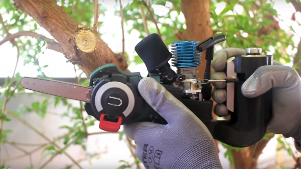
When life hands you the world’s smallest chainsaw, what’s there to do except make it even more ridiculous? That’s what [JohnnyQ90] did when he heavily modified a mini-electric chainsaw with a powerful RC car engine.

The saw in question, a Bosch EasyCut with “Nanoblade technology,” can only be defined as a chainsaw in the loosest of senses. It’s a cordless tool intended for light pruning and the like, and desperately in need of the [Tim the Toolman Taylor] treatment. The transmogrification began with a teardown of the drivetrain and addition of a custom centrifugal clutch for the 1.44-cc nitro RC car engine. The engine needed a custom base to mount it inside the case, and the original PCB made the perfect template. The original case lost a lot of weight to the bandsaw and Dremel, a cooling fan was 3D-printed, and a fascinatingly complex throttle linkage tied everything together. With a fuel tank hiding in the new 3D-printed handle, the whole thing looks like it was always supposed to have this engine. The third video below shows it in action; unfortunately, with the engine rotating the wrong direction and no room for an idler gear, [JohnnyQ90] had to settle for flipping the bar upside down to get it to cut. But with some hacks it’s the journey that interests us more than the destination.

This isn’t [JohnnyQ90]’s first nitro rodeo — he’s done nitro conversions on a cordless drill and a Dremel before. You should also check out his micro Tesla turbine, too, especially if you appreciate fine machining.

Continue reading “Micro Chainsaw Gets A Much Needed Nitro Power Boost”

Simple Mechanism Gives Support For SMT Assembly

With the fine work needed for surface-mount technology, most of the job entails overcoming the limits of the human body. Eyes more than a couple of decades old need help to see what’s going on, and fingers that are fine for manipulating relatively large objects need mechanical assistance to grasp tiny SMT components. But where it can really fall apart is when you get the shakes, those involuntary tiny muscle movements that we rarely notice in the real world, but wreak havoc as we try to place components on a PCB.

To fight the shakes, you can do one of two things: remove the human, or improve the human. Unable to justify a pick and place robot for the former, [Tom] opted to build a quick hand support for surface-mount work, and the results are impressive considering it’s built entirely of scrap. It’s just a three-piece arm with standard butt hinges for joints; mounted so the hinge pins are perpendicular to the work surface and fitted with a horizontal hand rest, it constrains movement to a plane above the PCB. A hole in the hand rest for a small vacuum tip allows [Tom] to pick up a part and place it on the board — he reports that the tackiness of the solder paste is enough to remove the SMD from the tip. The video below shows it in action with decent results, but we wonder if an acrylic hand rest might provide better visibility.

Not ready for your own pick and place? That’s understandable; not every shop needs that scale of production. But we think this is a great idea for making SMT approachable to a wider audience.

Continue reading “Simple Mechanism Gives Support For SMT Assembly”

Amazing Mechanical Linkages And The Software To Design Them

Most of us are more bits-and-bytes than nuts-and-bolts, but we have the deepest appreciation for the combination of the two. So, apparently, does [rectorsquid]. Check out the design and flow of his rolling ball sculpture (YouTube, embedded below) to see what we mean. See how the arms hesitate just a bit as the ball is transferred? See how the upper arm gently places it on the ramp with a slight downward gesture? See how it’s done with one motor? There’s no way [rectorsquid] designed this on paper, right?

Of course he didn’t (YouTube). Instead, he wrote a simulator that lets him try out various custom linkages in real time. It’s a Windows-only application (sigh), but it’s free to use, while the video guides (more YouTube) look very comprehensive and give you a quick tour of the tool. Of special note is that [rectorsquid]’s software allows for sliding linkages, which he makes very good use of in the rolling ball sculpture shown here.

We’ve actually secretly featured [rectorsquid]’s Linkage software before, in this writeup of some amazing cosplay animatronic wings that used the program for their design. But we really don’t want you to miss out if you’re doing mechanical design and need something like this, or just want to play around.

If you’d like to study up on your nuts and bolts, check out our primer on the ubiquitous four-bar linkage, or pore through Hackaday looking for other great linkage-powered examples, like this automatic hacksaw or a pantograph PCB probe for shaky hands.

Anyone know of an open-source linkage simulator that can also output STL files for 3D printing? Or in any format that could be easily transformed into OpenSCAD? Asking for a “friend”.

Continue reading “Amazing Mechanical Linkages And The Software To Design Them”