Using The Pyroelectric Effect To Identify Broken MLCC Capacitors

Vintage computer hardware can fail in a variety of fascinating ways, with [Bits und Bolts] dealing with an interesting failure mode, in the form of degraded MLCC capacitors on Voodoo 2 graphics cards. These little marvels of miniaturized surface-mount technology enable the placement of ceramic capacitors with very little space required, but as they degrade over time or due to physical damage, they can cause big issues in a circuit.

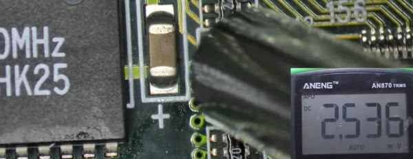
In the case of the two Voodoo 2 GPUs that [Bits und Bolts] was trying to fix, the clue that something was wrong was graphical glitches, which seemed to be related to something dragging down the 5V rail. Using the standard ‘inject voltage and see what gets hot’ method, he discovered a couple of dead MLCCs and replaced them. But something was still dragging the rail down. Unfortunately, whatever it was wasn’t enough to heat up the part in question, and no sane person wants to desolder hundreds or even thousands of MLCCs on a PCB and see whether it makes a difference.

Ultimately, the pyroelectric effect was used to hunt down the culprit, saving countless hours of work. This is a property of certain naturally electrically polarized crystals, in which the material generates a voltage when heated or cooled. Materials like that used in MLCCs, for example.

Continue reading “Using The Pyroelectric Effect To Identify Broken MLCC Capacitors”

A pink sine wave is seen against the black background of an oscilloscope display.

Coping With Disappearing Capacitance In A Buck Converter

Designing a circuit is a lot easier on paper, where components have well-defined values, or lacking that, at least well-defined tolerances. Unfortunately, even keeping percentage tolerances in mind isn’t always enough to make sure that circuits work correctly in the real world, as [Tahmid] demonstrates by diagnosing a buck converter with an oddly strong voltage ripple in the output.

Some voltage ripple is an inherent feature of the buck converter design, but it’s inversely proportional to output capacitance, so most designs include a few smoothing capacitors on the output side. However, at 10 V and a 50% duty cycle, [Tahmit]’s converter had a ripple of 0.75 V, significantly above the predicted variation of 0.45 V. The discrepancy was even greater at 20 V.

The culprit was the effect of higher voltages on the ceramic smoothing capacitors: as the voltage increases, the dielectric barrier in the capacitors becomes less permittive, reducing their capacitance. Fortunately, unlike in the case of electrolytic capacitors, the degradation of ceramic capacitors performance with increasing voltage is usually described in specification sheets, and doesn’t have to be manually measured. After finding the reduced capacitance of his capacitors at 10 V, [Tahmid] calculated a new voltage ripple that was only 14.5% off from the true value.

Anyone who’s had much experience with electronics will have already learned that passive components – particularly capacitors – aren’t as simple as the diagrams make them seem. On the bright side, they are constantly improving.