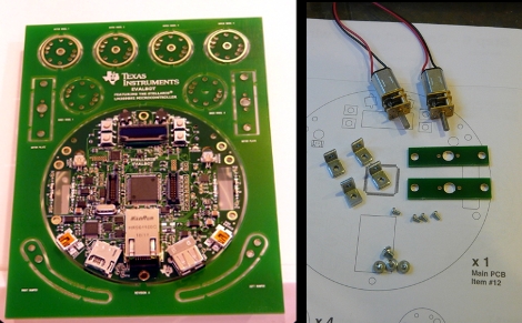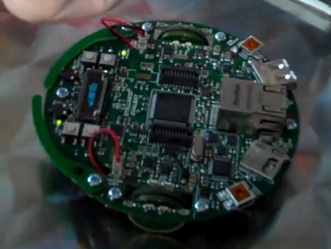
[Riley Porter] posted a picture of his EvalBot USB power hack. In the photo above we’ve put a box around D6 and D7. The development board ships with a 0 Ohm resistor in the D7 location, patching in power from the USB-B connector labeled USB DEVICE. He found that by moving that resistor to D6 he can power the board from the USB-B connector labeled ICDI.
That connector is the In-Circuit Debug Interface. TI sent us an EvalBot bundle so we pulled it out and tried it ourselves. If you plug in the ICDI it doesn’t power the board, and no USB devices register. Shorting the D6 pads changes this and the following USB device registers:
Bus 002 Device 062: ID 0403:bcd9 Future Technology Devices International, Ltd Stellaris Evaluation Board
So it looks like you need to have two USB connections or be using batteries in order to program the board via USB. The uC/OS-III hardcover book that ships with the EvalBot bundle includes board schematics. We took a look and were surprised to see that they show diodes installed on both pads. Rev A of the online schematics have been corrected, showing an omitted diode on D6 and the 0 Ohm resistor on D7. Images of both schematics are included after the break.
It would have been nice to see a selector switch installed here to give you a little more flexibility when prototyping.
Continue reading “Moving A Resistor For EvalBot Power When Programming”


