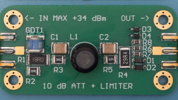
The HP 11947A is something of a footnote in the back catalogue of Hewlett Packard test equipment. An attenuator and limiter with a bandwidth in the megahertz rather than the gigahertz. It’s possible that few laboratories have much use for one in 2019, but it does have one useful property: a full set of schematics and technical documentation. [James Wilson] chose the device as the subject of a clone using surface mount devices.
The result is very satisfyingly within spec, and he’s run a battery of tests to prove it. As he says, the HP design is a good one to start with. As a device containing only passive components and with a maximum frequency in the VHF range this is a project that makes a very good design exercise for anyone interested in RF work or even who wishes to learn a bit of RF layout. At these frequencies there are still a significant number of layout factors that can affect performance, but the effect of conductor length and stray capacitance is less than the much higher frequencies typically used by wireless-enabled microcontrollers.


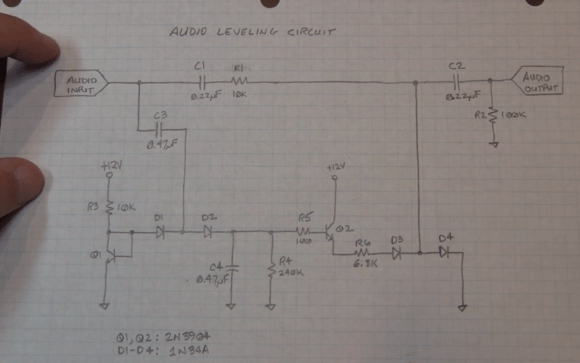
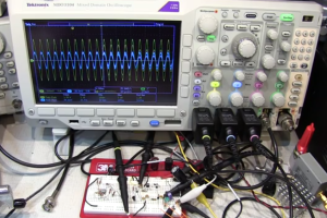
 ircuit isn’t new, he states right in the video that various audio limiting, compressing, and automatic gain control circuits have been passed around the internet for years. What he’s brought to the table is his usual flair for explaining the circuits’ operation, with plenty of examples using the oscilloscope. (For those that don’t know, when [Alan] isn’t building circuits for fun, he’s an RF applications engineer at Tektronix).


