A Modern Take On A Piece Of Old Test Equipment

The HP 11947A is something of a footnote in the back catalogue of Hewlett Packard test equipment. An attenuator and limiter with a bandwidth in the megahertz rather than the gigahertz. It’s possible that few laboratories have much use for one in 2019, but it does have one useful property: a full set of schematics and technical documentation. [James Wilson] chose the device as the subject of a clone using surface mount devices.

The result is very satisfyingly within spec, and he’s run a battery of tests to prove it. As he says, the HP design is a good one to start with.   As a device containing only passive components and with a maximum frequency in the VHF range this is a project that makes a very good design exercise for anyone interested in RF work or even who wishes to learn a bit of RF layout. At these frequencies there are still a significant number of layout factors that can affect performance, but the effect of conductor length and  stray capacitance is less than the much higher frequencies typically used by wireless-enabled microcontrollers.

A DIY Step Attenuator, By Gluing Together Two Smaller Ones

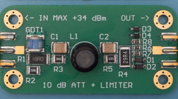
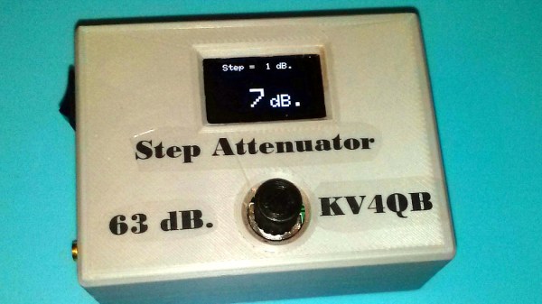
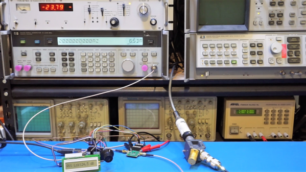
In the RF world, attenuators are a useful test and measurement tool. Variable units that can apply different levels of attenuation in discrete steps are even better. [DuWayne] made a 63 dB step attenuator by putting two smaller units in series, with an Arduino Nano in control of them. With a 3D printed enclosure and OLED for feedback, the device is easily adjusted with a single rotary encoder. There was even room to add a micro USB plug for recharging the power supply.

The two smaller digital attenuators [DuWayne] used are essentially breakout boards for the PE4302 digital RF attenuator, and cheaply available from the usual overseas sources. They are capable of up to 31.5 dB of attenuation in 0.5 dB steps, and by using two in series (and controlling them in parallel) [DuWayne] gets a range of up to 63 dB. The design files can be downloaded from a Dropbox share for the project, should you wish to try any of it for yourself.

Are you interested in RF and maybe software defined radio (SDR)? We’ve covered all the stuff you’ll need to get started with an inexpensive RTL-SDR, and sooner or later you may find yourself in need of [Dan Maloney]’s info on cheap and effective dummy loads.

Digital Attenuator Goes From Manual To Arduino Control

[Kerry Wong] comes across the coolest hardware, and always manages to do something interesting with it. His widget du jour is an old demo board for a digital RF attenuator chip, which can pad a signal in discrete steps according to the settings of some DIP switches. [Kerry]’s goal: forget the finger switch-flipping and bring the attenuator under Arduino control.

As usual with his videos, [Kerry] gives us a great rundown on the theory behind the hardware he’s working with. The chip in question is an interesting beast, an HMC624LP4E from Hittite, a company that was rolled into Analog Devices in 2014. The now-obsolete device is a monolithic microwave integrated circuit (MMIC) built on a gallium arsenide substrate rather than silicon, and attenuates DC to 6-GHz signals in 64 steps down to -31.5 dBm. After a functional check of the board using the DIP switches, he whipped up a quick Arduino project to control the chip with its built-in serial interface. It’s just a prototype for now, but spinning the encoder is a lot handier than flipping switches, and once this is boxed up it’ll make a great addition to [Kerry]’s RF bench.

If this video puts you in an RF state of mind, check out some of [Kerry]’s other videos, like this one about temperature-compensated crystal oscillators, or the mysteries of microwave electronics.

Continue reading “Digital Attenuator Goes From Manual To Arduino Control”

Pi Network Attenuators: Impedance Matching For The Strong Of Signal

If you catch a grizzled old radio amateur propping up the bar in the small hours, you will probably receive the gravelly-voiced Wisdom of the Ancients on impedance matching, antenna tuners, and LC networks. Impedance at RF, you will learn, is a Dark Art, for which you need a lifetime of experience to master. And presumably a taste for bourbon and branch water, to preserve the noir aesthetic.

It’s not strictly true, of course, but it is the case that impedance matching at RF with an LC network can be something of a pain. You will calculate and simulate, but you will always find a host of other environmental factors getting in the way when it comes down to achieving a match. Much tweaking of values ensues, and probably a bit of estimating just how bad a particular voltage standing wave ratio (VSWR) can be for your circuit.

Continue reading “Pi Network Attenuators: Impedance Matching For The Strong Of Signal”

RF Biscuit Is A Versatile Filter Prototyping Board

As anyone who is a veteran of many RF projects will tell you, long component leads can be your undoing. Extra stray capacitances, inductances, and couplings can change the properties of your design to the point at which it becomes unfit for purpose, and something of a black art has evolved in the skill of reducing these effects.

RF Biscuit is [Georg Ottinger]’s attempt to simplify some of the challenges facing the RF hacker. It’s a small PCB with a set of footprints that can be used to make a wide range of surface-mount filters, attenuators, dummy loads, and other RF networks with a minimum of stray effects. Provision has been made for a screening can, and the board uses edge-launched SMA connectors. So far he’s demonstrated it with a bandpass filter and a dummy load, but he suggests it should also be suitable for amplifiers using RF gain blocks.

Best of all, the board is open source hardware, and as well as his project blog he’s made the KiCad files available on GitHub for everyone.

It’s a tough challenge, to produce a universal board for multiple projects with very demanding layout requirements such as those you’d find in the RF field. We’re anxious to see whether the results back up the promise, and whether the idea catches on.

This appears to be the first RF network prototyping board we’ve featured here at Hackaday. We’ve featured crystal filters before, and dummy loads though, but nothing that brings them all together. What would you build on your RF Biscuit?