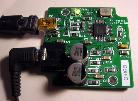
[Simon B] enters our 2024 Business Card Challenge with BAUDI/O, a genuinely useful audio output device. The device is based around the PCM2706 DAC, which handles all the USB interfacing and audio stack for you, needing only a reference crystal and the usual sprinkling of passives. This isn’t just a DAC board, though; it’s more of an audio experimentation tool with two microcontrollers to play with.
The first ATTiny AT1614 is hooked up to a simple LED vu-meter, and the second is connected to the onboard AD5252 digipot, which together allows one to custom program the response to the digital inputs to suit the user. The power supply is taken from the USB connection. A pair of ganged LM2663 charge-pump inverters allow inversion of the 5V rail to provide the necessary -5 V for the output amplifiers. This is then fed to the LM4562-based CMoy-type headphone amplifier. This design has a few extra stages, so with a bit of soldering, you can adjust the output filtering to suit. An LM1117 derives 3.3 V from the USB input to provide another power rail, mostly for the DAC.
There’s not much more to say other than this is a nice, clean audio design, with everything broken out so you can tinker with it and get exactly the audio experience you want.


