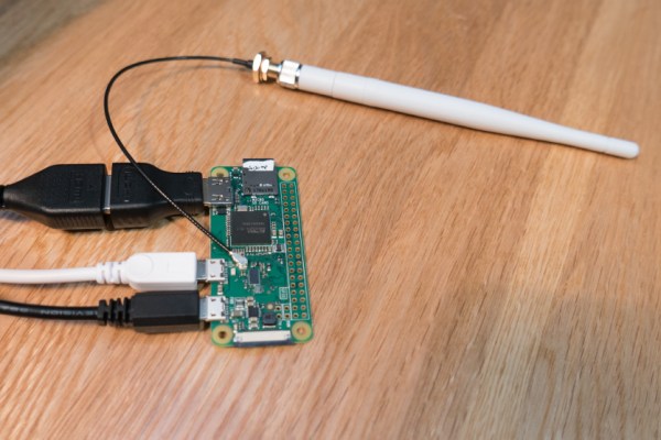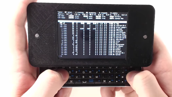
There’s something to be said for economies of scale and few things sell more than cell phones. Maybe that’s why [NODE] took inspiration from an iPhone slide out keyboard case to create this Pi Zero W-based portable terminal. This is actually his third iteration, and in the video below he explains why he has built the new version.
By housing the custom bits in a 3D-printed frame that is size compatible with the iPhone, [NODE] manages to leverage the slick slide out keyboard cases available for the phone. The iPhone in question is an older iPhone 5, so the cases are inexpensive, compared to the latest generation. On the other hand, the iPhone 5 is recent enough that it shouldn’t be hard to find a compatible case.
The circuitry itself is pretty straightforward: a battery, a charge controller, and an LCD display. The only complaint we could see was the lack of a control key on the keyboard.
Continue reading “Pi Zero W Impersonates IPhone, Becomes Terminal”
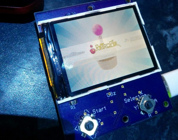
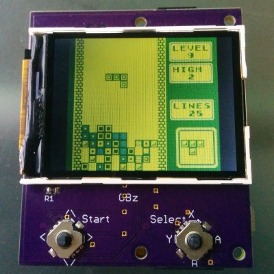 This build is based on the Pi Zero and a 2.2″ (0.56 dm) ili9341 TFT display. This display has a resolution of 240×320 pixels, which is close enough to the resolution of the systems the Pi Zero can emulate. The Pi Zero and display are attached to a beautiful purple breakout board (