[Semicolo] has a bunch of old PSUs on hand which he pulled out of some Lexmark dot matrix printers. In their stock form they put out 40V, which is close to the 35V max he needs to run the stepper motors on a 3D printer he’s been building. So he reverse engineered the PSU to change its output.
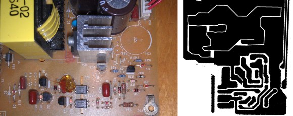
On the left you can see the top of the PCB. [Semicolo] flipped it over and snapped a picture of the traces on the bottom of the board. With a bit of work in The Gimp (FOSS image editing software) he was able to convert the traces to black and white. Overlaying the picture of the top with a 50% transparency of the traces made it rather easy see the connections and generate a schematic for the hardware. That’s a really cool trick!
Figuring out how it’s supposed to work is a big step in achieving his goal. The next step was to see if he could bend the circuit to his will. He had previously run across ATX PSU hacks which changed the reference voltage in order to alter the output. He grabbed a datasheet for the HA17431 variable shunt regulator. It lays out how to tune the output based on values of a few external components. He dropped in one resistor and the output measured 31V, well within his target range.


