Instead of numbers the IN-15A Nixie tube has symbols, specifically n, μ, P, -, +, m, M, k, Π, and %. The related IN-15B Nixie has letters: A, F, H, Hz, Ω, S, V, and W. These should look familiar to you. [kittan] decided it would be really cool to have a Nixie-equipped multimeter, and since he’s going retro fabulous anyway, he might as well make his multimeter controllerless, with discrete logic and comparator ICs. It’s a state-based Nixie multimeter, and it’s going to be freakin’ awesome.
The basic plan of the multimeter is a precision 1V voltage reference, a bunch of opamps, and a ton of resistors to form a ladder All the opamps in each decade are XOR’d together, so when one of the ten comparators for each decade stage is tripped, only one number will display on the (numeric) Nixie tube.
With a reasonable plan for measuring a voltage, it’s not too hard to expand the design for other measurements. V=IR, so with a constant current, V=R. The same equation can be used with a fixed resistance to determine current. Capacitance can be measured by comparing the change in charge of a known capacitor. Inductance, conductance, power, and frequency are all planned for this monster of a multimeter.
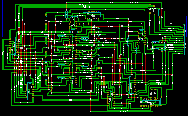
The initial PCB design is completed (and shown above) and it’s theoretically possible to do on a single-sided board with a minimum of jumpers. An amazing project, and even though you could probably find a similar, ancient meter in a trash heap or on a collector’s shelf, this is by far one of the best Nixie projects we’ve ever seen.


