When [Alain] wanted to use some of the new TinyAVR 0 chips — specifically, the Attiny406 — it seemed overkill to use the Windows IDE. There are plenty of sources of information on programming other AVR chips using simple command line tools, but not for these newer 0-series parts which use a new programming protocol known as UPDI. That led to a deep diving into how to program a TinyAVR 0 with a text editor, makefile, and USB-to-serial cable.
The Attiny406 has 4K of flash, 256 bytes of RAM and can run at 20 MHz with no external clock. You might think programming would be similar to a regular AVR part, but these tiny devices use UPDI (Unified Programming and Debug Interface) which uses 3 pins for programming. Older devices used different protocols.
It is very easy to create a UPDI programmer. A USB to logic-level serial cable and a 4.7K resistor is all it takes. There’s Python code that knows how to drive the protocol, too. You can also use the logic-level serial port on the Raspberry Pi with some device tree modifications explained in the code’s documentation.
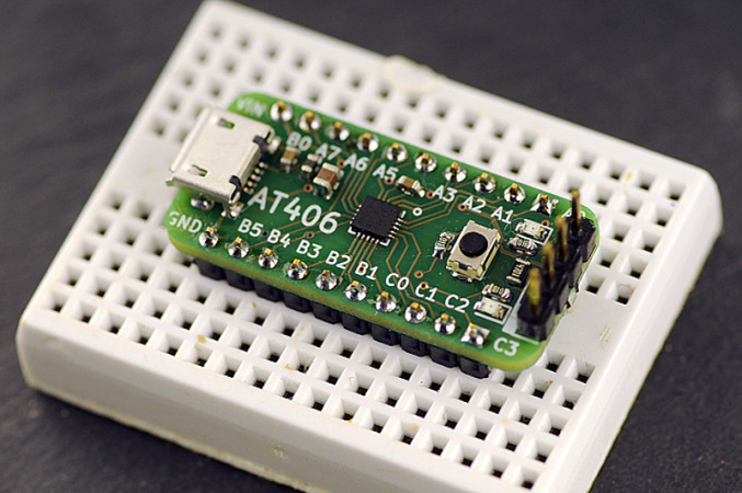
[Alain] made a nice breakout board for the device. It fits a breadboard, allows for 5V or 3.3V operation, and has an LED and switch. Nothing fancy, but handy. Once you know how to ship a hex file to the chip, the rest is pretty standard. While the AVR version of gcc doesn’t cross-compile for the ATTiny out of the box, there is a device pack from Microchip that enables that feature.
The trend is to go to bigger processors, not smaller, but when you need to cram something in a small space, save a few pennies per unit, or draw very little power, these tiny processors can be just the ticket. The processors may be small, but if you work you can do some pretty big things with them.


