We’ve discussed MIDIboxes before (and once before that), but we’ve never really told you what goes into them or how to build one. We’ll take you through the process after the break.
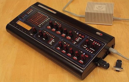
This particular MIDIbox by [Subatomic] is built on the MIDIbox SID specs originally conceived by [Thorsten Klose] (check out the great sound samples) and streamlined by [Wilba]. It uses a Commodore 64 case, 8 of its SID chips, and the power supply, but gets most of its other parts from various different sources. The Commodore’s SID or Sound Interface Device, was one of the first sound chips available in a personal computer.
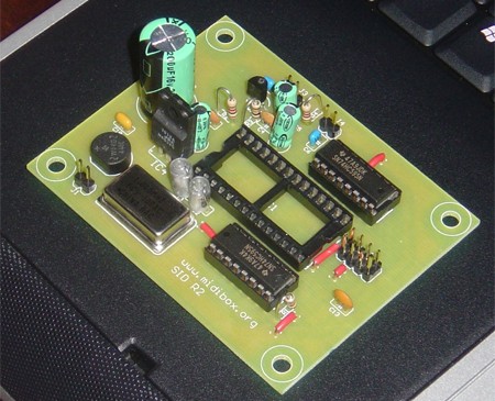
In the worklog, a SID module, the first of four, was built before anything else. Then [Subatomic] opened up the Commodore case and attempted to fit a number of modules into it. For the MIDIbox’s power, he converted the original Commodore power supply to provide 14VDC and 5VDC, but learned much later that this would only give enough power for 4 SIDs, resulting in a mono MIDIbox. He continued by adding a power board and noting that with the core and SID modules and the audio mixer board, it’s a tight but workable fit.
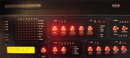
The next several steps involved designing and building the control surface. After creating a mockup and acquiring several components like knobs, LEDs, and a small LCD, [Subatomic] began building many of the necessary control surface PCBs, including the filter control PCB and a few others.
[Subatomic] went on by going through the painstaking process of creating backlights for the knobs. After that he acquired the custom-made front panel, created the LCD module, and attached it and several PCBs to the panel. The panel was then painted.
After a little work on the PSU and the rear I/O panel, [Subatomic] prepped some banksticks (external storage accessories; think USB stick forerunners with a female serial jack).
After finishing and gluing the LEDs to the knobs, the panel was finished. At this point Subatomic decided to scrap the SID, core, din and dout modules in favor of a single PCB that does everything. He cut the board to make it fit in the case, cut headers, added resistors, burned out the LCD, did a lot of spot-checking on the wiring, and then he finally added the SIDs to the board.
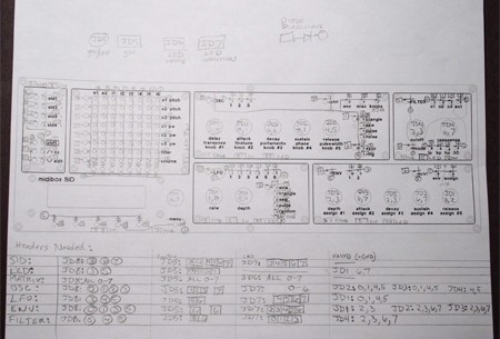
He soon zeroed in on the power supply problem that was only routing enough power to 4 SIDs by replacing the malfunctioning C64 PSU with a good one, after which the LCD was also replaced. The wiring diagram above shows how the remaining modules would be wired to the main board.
The only software work involved adding functions for 2 special buttons to the preexisting firmware and recompiling it. He realized that the MIDIbox was missing a mixed output jack, so he added than and made several minor cosmetic mods. With these final fixes, the MIDIbox SID was completed. If you’re considering this project, be aware that it’s a major endeavor with a lot of detail work that took [Subatomic] nearly 3 years to build, but the reward is a slick-looking, fully functional MIDIbox SID of your own.
[via Matrixsynth]


It looks cool, but I would hate to hack up one of my C64’s. I only have 4 after all, and you never know when you will need one to save the day.
“malfunctioning C64 PSU”
I chuckled when I read this. I’ve read that back in the day, C64 users learned about how dodgy these were early on. Replacement (reliable) PSUs were available on the after-market soon thereafter. To wit, I once purchased a complete C64 setup (w/dust covers!) from one such user where the original PSU was nowhere to be found.
There were also chronic overheating problems with various chips, including the SID thanks to the C64 “breadbox” design. Here’s to hoping that midibox has a good thermal design!
That’s an awesome looking project.
I certainly wouldn’t recommend using a C64 power supply for, well, anything. Even in their original job they ran hot and frequently failed, and their linear design wastes a lot of power. Power supply technology has come a long way.
I’ve tried this project already but had problem with the bootloader system… maybe because I didnt have an LCD at the time…
Well anyway I redid the project on my own on a Atmega164P instead.
Got love those SID chips, they sound so fat.
Hi there,
I see your posts are quite old, however it seems we have run into the same issues concerning the gate off on 8580s chips. I can’t find any other related threads, so i hope that you’ll read these messages and enlighten me.
I’m building my own synth SID for my own pleasure and for the final exam of my bachelor’s degree in electronics.
The electroncis are working fine and I have made a rudimentary user interface and sequencer which is triggering notes and so on. I encounter two issues :
1/ when playing a note, putting the gate off in the control register does trigger the release of the VCA, however, the note never stops, unless i select no wave form ( 0b0000XXXX in the control register).
2/ And the second problem is when i attempt to change the output volume of the chip. When i do that, the oscillator two shuts off (osc3 remains active, osc1 i don t know, it seems it does not work, but i might have screwed up somewhere in my code).
Have you solved your gate issue, is the datasheet correct?
If you read this, please reply on my email adress : zet0korp@gmail.com
Best regards,
David
Most people who are building Midibox SIDS at the moment aren’t ripping apart old C64s for the SID chips. Wilba has managed to source old 6582 chips (probably designed as a replacement for failed 8582 SIDs)and is supplying them to the community. i don’t know how he’s done it, but he’s sold on 1000’s of them!
That is really well done, it looks pro!
I never had a c64, but it’s tempting now…