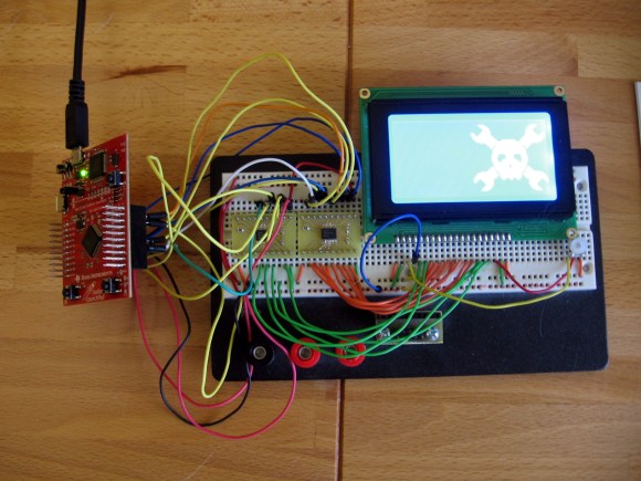
I finally set aside some time for one of my own projects. I have been playing around with ARM microcontrollers a lot lately and wanted to try out my GLCD display that uses the KS0108 protocol. It’s 5V but I had heard that some of these displays will work with 3.3V TTL. But the datasheet tells me otherwise. I tried using a pull-up resistor to 5V and configuring the Stellaris Launchpad pins to open drain, but the low voltage wasn’t getting below the 0.3V threshold needed by my display. My only choice was to use some type of level conversion. I actually ended up driving the KS0108 using a pair of TXB0108 level converters.
I figured this had to have been done before so I check over at Sparkfun. Their offerings are either one-way or have a direction pin that you must drive yourself. I figured there had to be a bi-directional solution and a search over at Mouser led me to the TXB0108. It is exactly what I was looking for and as you can see I etched my own circuit boards to make the TSSOP chips breadboard compatible. I’ve documented the process you can find the code and board files at my post linked above.
Update: one of the Reddit comments mentions this chip is available on a breakout board from Adafruit if you’re interested.


For my money the TXB series are only way to fly when it comes to level conversion.
Depends on whether you have I²C, SPI or whatnot.
There’s also http://ics.nxp.com/support/documents/interface/pdf/an97055.pdf resp. http://www.rocketnumbernine.com/2009/04/10/5v-33v-bidirectional-level-converter, which might be much easier…
In addition to Adafruit’s breakout board for the TXB0108, they also carry a breakout board using FETs (http://adafruit.com/products/757). It’s intended for I2C level conversion, since the TXB/TXS series direction sensing can get confused with the inclusion of pull-up or pull-down resistors (found that out the hard way). I’m still learning about this topic; in one project I have an Arduino TFT LCD shield at 5v, a Teensy 3.0 at 3.3v and a color sensing chip (TCS34717) which communicates over I2C at 1.8V. That being said, for most applications, if you can get the connections right the TXB/TXS series is definitely the way to go.
Texas Instruments have a very flexible I2C level converter in SOIC8 : the PCA9517 , also made by NXP, it seems.
That chip looks like a good packaged solution, although I am a bit more partial to the ‘simplicity’ of the FET design. I’m still trying to find some reasonable solutions to High Speed (3.4 MHz) I2C though, since neither the chips discussed or the FET solutions work well there.
I’ll second this post. The FET based solution has been around for many years and seems to work well. I even built a version of this for a breadboard by soldering wires onto surface mount FETs I had on hand in the parts bin.
Can you clarify the bit about the 0 ohm resistor between PD and PB
Check out the schematic on page 20 of the datasheet:
http://www.ti.com/lit/ug/spmu289a/spmu289a.pdf
Right in the middle you’ll see that PD0 is connected to PB6 and PD1 is connected to PB7.
Looking at the data sheet it looks like they are only used to give compatibility to msp430 booster packs. Would that not affect the overall usage of pb6 and pb7 at the same time as pd0 and pd1.
Bidirectional Level-Converters with autosensing are a bit slower, you can’t go high speed with them. Texas Instruments has a big range of products there (surprise) and i got myself some of those with direction pins for use with SPI (µSD-Card to Atmega32u4) which would not work properly with autosensing converters.
I’ve been using the TXS0104E from TI for a while now to nterface between 5V & 3.3V.
The SO14 package makes it easy to flywire to if you need to.
I’m continuously surprised about how little and uninteresting projects with ARM based boards are, it’s all things you could do with an arduino or even an atiny.
But then I realize I myself also lack in the imagination department sand I’m all understanding again.
It’s frustrating though. I like to be awed more :)
and* not ‘sand’, sorry
[Mike Szczys], regarding this:
“But I still get some garbage on the display from time to time. This can usually be fixed by straightening out the jumper wires, which is what makes me thing it is a cross talk problem.”
Could be. Another possibility is that some of your breadboard or female header connectors aren’t making a decent connection, which I find more common in recent years as both become more cheaply made. Rearranging wires can make it better (or worse), as it changes the tension on the connection.
Fortunately, you don’t need an oscilloscope to diagnose this. Attach a 2.2K resistor across the terminals of a piezo tweeter. Output a steady, active logic high (or low if needed) at the source on all signal lines you want to check. Connect one terminal of the piezo to a signal destination, and the other terminal to ground (or VCC, if the signal is driven low). Wiggle the wire and connector. You’ll be able to hear the slightest fault as a crackle. Repeat with remaining signals.
Piezo tweeters are very useful as cheap test equipment. Connected between VCC and GND (without the resistor of course), I’ve also used them to find locations where supply rails sag, and need additional bypass capacitors. And tracked the source of noise in an audio circuit to a poor switching power supply. I can hear fluctuations as small as 10mV in a quiet room, with the tweeter near my ear. In some cases, it will also reveal issues in digital signals, especially repetitive ones; for example, glitches or jitter in a PWM signal are easily heard.
This is a good example of why you should go to Adafruit first next time.
And here I just do it with some 2N7000 transistors and a few resistors because I’m a uncreative bastard who hates SMD.
An example of it: http://www.hobbytronics.co.uk/mosfet-voltage-level-converter
I’ve used these before, they’re cheap ($0.48) 20pin DIP and have worked for my needs.
http://www.digikey.com/product-detail/en/SN74LVC244AN/296-8501-5-ND/377479
I’ve got the original MSP430 launchpad at 3.3V driving a string of WS2801 LED drivers running at 5V. Out of spec but it will run fine at 4Mhz (not 8,certainly not the 25 from the datasheet). Hooray for de-rating.