Two-wire Serial Backpack For GLCD Screens

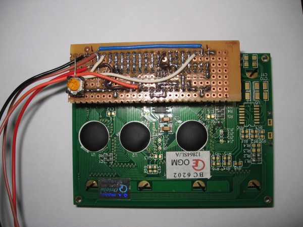
[Debraj] wrote in about his 2-wire serial backpack he developed for a Graphic LCD screen. It’s build on a hunk of protoboard and uses a pair of 595 shift registers to translate incoming serial data to the parallel interface which is used by the LCD screen. It takes more time to push commands this way, but the interface is still quite snappy as you can see in the clip after the jump.

The real trick here is how the hardware has been configured to get away without a third wire for latching the shift registers (if you need a primer on 595 chips check out this feature). The idea of using a latch is that all of the data can be shifted in over the serial pin before it appears on the output pins. Otherwise, the GLCD would see each bit as it shifts into the register, wreaking havoc on its communication protocol. [Debraj] gets around this by using a diode AND gate trick he learned from this other serial LCD project.

One good thing about this method is the 595 chips have a wide range of control voltage that will allow you to drive this with 3.3V or 5V microcontrollers. But you do need to implement the communication protocol and push those commands via serial. For nearly the same cost in chips something like an ATtiny2313 could be substituted to make an even simpler addressing scheme — or even switch to 1-wire protocol. But you’d then lose the wide input voltage tolerance.

Continue reading “Two-wire Serial Backpack For GLCD Screens”

GLCD Clock Project Packed With Great UI And Features

glcd-clock-packed-with-features

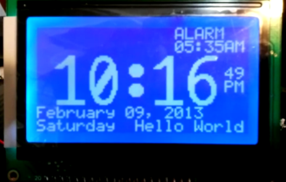
This Graphic LCD clock doesn’t have a fancy case, but [Gregory Wright] built in so many great features we think it will serve as inspiration for many projects to come. If he does decide to add a case it will be quite easy as there are no buttons to work around.

Without buttons how can the thing be adjusted? He decided to go with an IR remote control for all settings. This gives him a lot more options than a handful of buttons would have. Plus, heavy sleepers will need to find the remote control in order to shut off the alarm. We also think it’s interesting that the 595 shift registers he used have a low enough data high threshold (3.15V when VCC is 4.5V) that he didn’t need level converters to drive the 5V display with his 3.3V MSP430 Launchpad.

Check out his video after the break to learn about all the features he included in the UI. Our favorite is shown on the bottom right where it says “Hello World”. This is an area dedicated to a custom message for each day. He uses it to remind him about trash day (now there’s a feature!).

Continue reading “GLCD Clock Project Packed With Great UI And Features”

Level Converters To Make All Your Hardware (5.5V And Under) Play With Each Other

txb0108-level-converters-ks0108-stellaris-launchpad

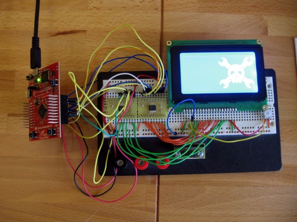
I finally set aside some time for one of my own projects. I have been playing around with ARM microcontrollers a lot lately and wanted to try out my GLCD display that uses the KS0108 protocol. It’s 5V but I had heard that some of these displays will work with 3.3V TTL. But the datasheet tells me otherwise. I tried using a pull-up resistor to 5V and configuring the Stellaris Launchpad pins to open drain, but the low voltage wasn’t getting below the 0.3V threshold needed by my display. My only choice was to use some type of level conversion. I actually ended up driving the KS0108 using a pair of TXB0108 level converters.

I figured this had to have been done before so I check over at Sparkfun. Their offerings are either one-way or have a direction pin that you must drive yourself. I figured there had to be a bi-directional solution and a search over at Mouser led me to the TXB0108. It is exactly what I was looking for and as you can see I etched my own circuit boards to make the TSSOP chips breadboard compatible. I’ve documented the process you can find the code and board files at my post linked above.

Update: one of the Reddit comments mentions this chip is available on a breakout board from Adafruit if you’re interested.

Control A TV With GLCD Commands

[youtube=http://www.youtube.com/watch?v=t3gMjuVdQnA]

This hack lets you use a TV in place of a graphic LCD screen. But we like to think of this less as a replacement for a GLCD and more of a simple way to get your information onto a television. A PIC 18F452 acts as a translator between the GLCD parallel inputs and a composite video output. There are some malformed image links on the page which we’ve fixed and linked to after to the break so that you can take a look at the schematic, component layout, and PCB artwork. The assembler code and hex file are available for download but you’ll need to register to get access to them.

Working image links:

[Thanks Flacoclau]