[Jordan Wills] got tired of being limited to eight pixels of resolution and having jumper wires littering his work space. He set out to upgrade his Stellaris Launchpad frequency analyzer project using booster packs. You may remember the initial iteration of the project which used an 8×8 LED matrix to map audio spectrum. With this upgrade he’s really putting the power of that ARM chip to use.
His first improvement with this project was to spin his own audio input board. It has a standard headphone jack for input and a few passive components to shift the signals to rest nicely within the ADC measurement range. The shield has two double pin headers and a group of four stand offs to serve as legs. This way it plugs into the female headers on the bottom of the Launchpad and provides a stable base for the assembly.
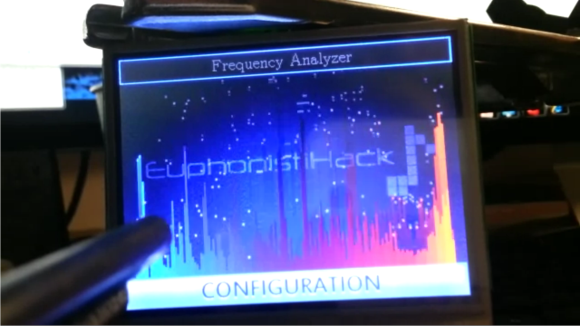
The second portion of the setup is an LCD booster pack for the hardware. Kentec manufactures this 3.5″ 320×240 LCD (EB-LM4F120-L35) complete with a resistive overlay making it touch sensitive. The increase in resolution, and availability of different colors gave [Jordan] plenty to work on. Since this add-on is designed for the Launchpad and has a driver library already available he was able to focus on adapting the FFT output for display and adding in new features. Don’t miss seeing what he’s accomplished in the clip after the break.


How accurate is it at close to $90 you could pretty much buy a better one
ya ya the part of putting your own together… still pretty cool
I’m sure one of two things will happen in time.
1) He’ll build it into his hi-fi system, providing a spiffy spectrum display that’s unique and personalized; which you cannot buy at any price. Given the name of his website, it’s quite possible this is what he’s aiming for.
2) Or he’ll tire of it, and having learned all he can from the project (and passed that knowledge along to us), will recycle the parts for other projects. It’s certainly worth $50 to have a really nice screen on hand for MCU experiments.
This comment makes me so very, very sad =/
The point of this project, and my personal motivation for completing it, has absolutely nothing to do with cost. After months of coding, I have gained knowledge that I formerly did not have. I have gained experience that will be valuable for future projects. I now have something cool that I can sit on my desk to show off to friends and coworkers that makes me smile whenever I look at it.
Most importantly, though, I had fun pursuing a hobby that I passionately enjoy. The happiness I derived, both from late night coding sessions and from knowing that I did something genuinely cool and interesting (to me), far outweighs what money I have spent on materials.
In my opinion, if you’re setting out to do a project like this in your free time and your goal is to make or save a buck, you’re doing something wrong.
As far as your question about how accurate it is… read the writeup or look through my code and it will be easy to see for yourself.
sorry wasn’t my intention to make you sad. By all means learning is always a worthwhile but at the same time if you have to build it yourself it shouldn’t cost as much or more than a commercial offering it seems to me the places selling half of this stuff are ripping the home hobbyist off, not that its going to change or detracts what you’ve done here I did say it was cool.
*worthwhile endeavour
Love it when deadmau5 is used for videos :)
Looks super sharp, nice job.
I found it pretty disappointing to see that it had no real antialias filtering. That’s one of the things people are supposed to learn in the first week of a DSP course. There’s a single pole RC filter implicit in the level shifter, but that’s not adequate.
With proper antialiasing and a waterfall display it would be pretty cool though.
The source is there if you want to do it yourself :P
As to why I didn’t add that in, well… it has been a long, long time since my last DSP class, and I’m primarily a software guy. Honestly, I had to dig through a few wikipedia articles to even remember what the term anti-aliasing feature means…
The notion of creating a lowpass circuit on my signal conditioning booster pack that is capable of changing at runtime via digital potentiometer is interesting, but I fear pretty far beyond my current hardware design abilities.
I think that the CMSIS library from ARM contains an example of how to use their FIR filtering function as a lowpass filter though. I’m a bit concerned with how that would affect the resource usage of my code (I have lots of processor power to spare, but I’m currently running about 25 bytes under the 32K of RAM the LM4F120 contains). It sounds like that would make a pretty big difference in the display though, especially when using lower sampling frequencies. I’m hoping to get some free time during the holiday break coming up in a bit here; I’ll see if I can add that into my DSP loop :)
Also, if I remember correctly, the first week of my DSP course was spent covering the difference between cartesian and polar co-ordinate systems. It took us a bit to get to filters. :P
Reg is talking about a hardware filter prior to the ADC input, since that’s where you can prevent aliasing.
Wasn’t sure if you realized that – you mention a variable LPF in the signal conditioning circuitry, but you also talked about changing the source, which won’t help with aliased digital samples.
Bah, thanks for the clarification; I should not have tried to formulate an answer before I did my homework and got a full understanding of the underlying concepts.
At 26Khz digital sampling frequency (your default), in theory you need a low-pass analog filter prior to your ADC that effectively cuts off everything about 13Khz.
Fortunately, in practice real music contains very little signal amplitude above 13Khz. For an *audio* spectrum analyzer, rather than test equipment that may receive signals of any arbitrary frequency and amplitude, the little bit of noise aliasing adds to the display can be overlooked.
Sampling music at 4Khz would substantially increase aliasing. A tone at 4.5Khz would appear as 3.5Khz, 5Khz appears as 3Khz, and so on – a shifted and mirrored image of the true frequency. Sampling at 44.1Khz or higher virtually eliminates aliasing from music; unless your source is poorly designed, and produces high frequency and high amplitude artifacts itself.
It would be awesome if you could add a small mic preamp so you could use a measurement mic and have a small portable RTA.