A Li-Ion Booster Pack, Done Right

We’re all used to battery booster packs containing a Li-ion or Li-poly cell and a little inverter circuit, they are a standard part of 21st century daily survival for those moments when smartphone battery lives don’t perform as advertised. But how many of us have considered what goes into them, and further how many of us have sought to produce the best one possible rather than a unit built at the lowest price?

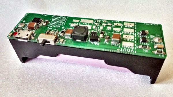
It’s a course [Peter6960] has followed, producing a PCB that sits on the back of an 18650 cell holder. It follows the work of [GreatScott] in particular in its use of the TP4056 charger, MT3608 boost converter, and FS312F protection ICs. Many commercial modules omit any protection circuit, and the FS312F is of particular interest because it has a low 2.9V cut-off voltage that should lengthen the life of the cell. Files for the PCB can be found in a zip file hosted on Google Drive.

You might think that there was nothing new that could be learned about a Li-ion battery booster, but it’s always worth a look at a well-executed piece of work. We noticed he refers to Li-poly cells while using what appears to be a Li-ion 18650 cell. Most likely this is merely an oversight.

There is a lot to know about the characteristics and safety of the lithium-chemistry rechargeables, you may find [Sean Boyce]’s article on the subject to be an interesting read.

Stellaris Launchpad And Booster Packs Used As Frequency Analyzer

stellaris-frequency-analyzer-using-booster-packs

[Jordan Wills] got tired of being limited to eight pixels of resolution and having jumper wires littering his work space. He set out to upgrade his Stellaris Launchpad frequency analyzer project using booster packs. You may remember the initial iteration of the project which used an 8×8 LED matrix to map audio spectrum. With this upgrade he’s really putting the power of that ARM chip to use.

His first improvement with this project was to spin his own audio input board. It has a standard headphone jack for input and a few passive components to shift the signals to rest nicely within the ADC measurement range. The shield has two double pin headers and a group of four stand offs to serve as legs. This way it plugs into the female headers on the bottom of the Launchpad and provides a stable base for the assembly.

The second portion of the setup is an LCD booster pack for the hardware. Kentec manufactures this 3.5″ 320×240 LCD (EB-LM4F120-L35) complete with a resistive overlay making it touch sensitive. The increase in resolution, and availability of different colors gave [Jordan] plenty to work on. Since this add-on is designed for the Launchpad and has a driver library already available he was able to focus on adapting the FFT output for display and adding in new features. Don’t miss seeing what he’s accomplished in the clip after the break.

Continue reading “Stellaris Launchpad And Booster Packs Used As Frequency Analyzer”