Let’s rollback the hobby electronics calendar a few decades with [myvideoisonutube’s] alarm activation control circuit using a matrix style phone keypad. The circuit is quite old using CMOS 4081 with 4 ‘AND’ gates to hardwire the access code. [myvideoisonutube] references [Ron’s] “Enhanced 5-Digit Alarm Keypad” schematic for this build changing the recommend keypad with a more common matrix style keypad found in touch pad phones. These types of matrix keypads wouldn’t work outright for the input so he cut some traces and added hookup wires to transform it into a keypad with common terminals and separately connected keys. We love seeing such hacked donor hardware even when it requires extensive modifications. [Ron’s] source circuit included a simple enough to build tactical button keypad if you can’t find a suitable donor phone.
Learning how to use mostly discrete components instead of a microcontroller would be the core objective to build this circuit outside of needing a key-code access point or other secure 12 V relay activated device. Such a device would be quite secure requiring a 4 digit “on” code and 5 digits for “off”. You couldn’t just pull off the keypad and hotwire or short something to gain access either. The 4 digit on “feature” does knock the security down quite a lot. However, all keys not in the access code are connected to the same point so you could increase your security by using a pad with more keys.
On [Ron’s] site you will find a detailed construction guide including top and bottom view for placement of all the components on veroboard. Join us after the break to watch [myvideoisonutube] demo his version.


It is nice, but he says you cannot activate the relay with access to the wires without access to the PCB or knowing the code.
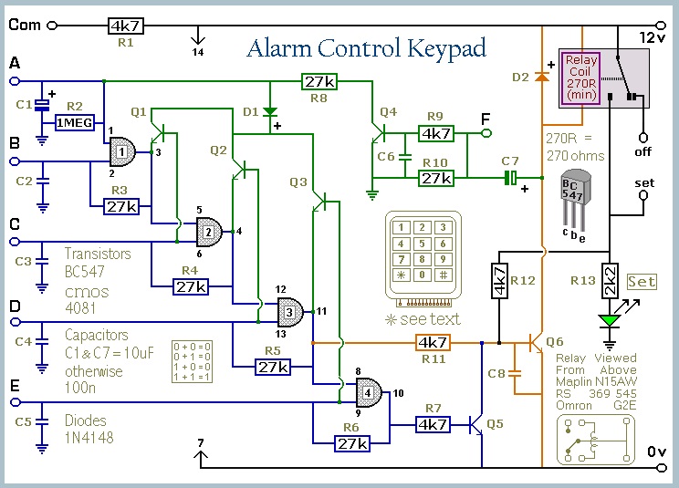
This is untrue, several wires will have zero ohm resistance between them, these will be the F wires.
Attach your multimeter between the common and one of the 5 non F-wires.
Touch that wire to the common, the multimeter will read 0V, release the common, it will either go back to 12V instantly, or it will do so slowly. The wire which does this slowly is the A wire.
Connect the A wire you found directly to the common wire. Connect your multimeter between A and F.
Out of the four remaining wires you connect each of them to the common. If you have the wrong B wire the voltage on your multimeter will drop (due to the transistor base-emitter junction pulling A to ground). If you do it with the B wire nothing will happen to the multimeter. Connect B together with A to the common.
Next you try from the three remaining wires which is C, in the same way. Do not permanently connect C, this may give problems with the transistor, just remember which button it is.
You now have just 2 possibilities left which is D. You can continue with the same method, or simply brute-force. Ofcourse you can also bruteforce once you know which wires are F, it’s only 32 possibilities after all.
Note: There are methods which require you to do it in less steps, but they require more movement of the multimeter which I assume takes more time than simply pushing buttons.
If you have access to the wires and a ground, all you need to do to to
drive point D high with an external power source. The B-E junction of Q2
will also drive current into “AND” gate 3. Gate 2 would try to pull that
pin low. It is old 4000 CMOS gate, so it wouldn’t take a lot of current
to overcome its output.
Very cool example of old tech designs, but honestly, a Picaxe is a better choice.
“simple enough to build tactical button keypad”
Tactical button keypad? TACTICAL? Is it available in black also? Hold my flashbang while I crack this code in record time.
At least they are not using indiscrete circuitry!
I downloaded this schematic over 6 years ago. Wow
I saw this done in a book I read 25 years ago, but in proper discretes. It used SCRs on the “correct” buttons, connected to a common power rail. Each SCR, I think, supplied current thru a button to the gate of the next one, so pressing them in sequence powered up the last SCR, which drove the load. The power rail was connected via a resistor to limit the available current. The “wrong button” connection, connected to all the wrong buttons in parallel, set off a different SCR that crowbarred the rail down to 0v, resetting the other SCRs.
I think this design needs separate buttons, can’t think how you could do it using a keypad with a common connection.
I also can’t remember how it managed to reset the circuit if the right button was pressed, in the wrong order. Dunno if it did or not. Without this feature, you’d still need to get the buttons in the right order with no wrong ones, but any of the “correct” buttons wouldn’t affect the circuit if pressed out-of-order.
Anyway it’s expandable to as many digits as you need for the code, just adding SCRs. And you can have as many “wrong” buttons too, just add buttons. And it’s discrete.
http://www.freepatentsonline.com/3739233.html
Good grief! It was patented in 1973! I wonder if the chap who wrote my book was the inventor, or the sneaky get just cobbled a dozen patents together into a teach-yourself electronics book!
I’m gonna look and see if he solved the “right button wrong order” problem, from the brief description looks like he didn’t.