Inverted Quadcopter? That generally means a crash is soon to follow. Not so for a new crop of quadcopter fliers. These new quadcopters are capable of sustained inverted flight. We’ve seen inverted quadcopters before here on hackaday. However, previous inverted quadcopters always used collective pitch to control the thrust produced by the blades. Collective pitch on a quadcopter is much simpler than it is on the main rotor of a traditional helicopter. R/C and full-scale helicopters mix collective and cyclic pitch to articulate the main rotor blades. A quadcopter only needs the collective portion, which is similar to a traditional helicopters tail rotor mechanism, or a variable pitch prop on an airplane.
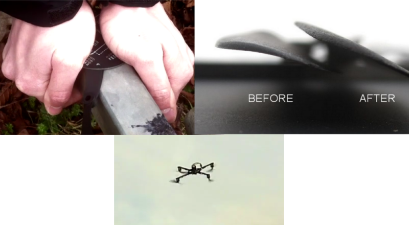
These new quadcopters are using a much simpler method of flying inverted: Spin the motors backwards. Quadcopters control their flight by quickly varying the speed of rotation of each motor. Why not completely reverse the motor then? Today’s brushless outrunner motors have more than enough power to quickly reverse direction. The problem becomes one of propellers. Standard propellers are designed to create thrust in one direction only. Every quadcopter uses two clockwise rotation and two counterclockwise rotation propellers. Propellers will generate reverse thrust if they are spun backwards, however they will not be as efficient as they would when spinning the direction they were designed for. The quad fliers have found a partial solution to this problem: Remove the curve from the blade. R/C propeller blades are sold by diameter and blade pitch. The pitch is a measure of the angle of attack of the blades. R/C blades also have an airfoil style curve molded into them. Removing this curve (but not changing the pitch) has helped the problem.
This final problem is control systems. Since quadcopters already are relying on computer control for basic flight, it’s simply a matter of loading custom firmware onto your flight board to support motor rotation reversal. Speed controls also have to be capable of reverse rotation, which means new firmware as well. We’re curious to see how the quadcopter community settles on the control systems for inverted flight. The R/C helicopter community went through several iterations of control systems over the years. At one point they were using “Invert switches” which reversed controls as well as handled the collective pitch changes. As time went on, these switches fell out of favor and are now known as “Crash switches” due to the result of accidentally hitting one while flying, or before engine start.
[Thanks Marc]


I wanted to build a quad with CCPM (System used by more advanced heli’s) but would be unable to pilot such a contraption
quadcopters are already unflyable by a human, hence the need for a IMU and microcontroller, why not let it handle the CCPM too?
wrong. many early quad pilots flew gyro multirotors. copters with one gyro on each arm assisting in partial stabilizing of that motor. there was no accelerometers to auto level the copter. it was all human input.
these days every new system has auto stabilize. turn that off and you can fly freestyle but most people dont know how.
any 3d heli pilot could flip a copter with those blades and fly it just fine pending the motors went in reverse.. but sure couldn’t :)
Loved the ending of second vid :)
flying lawnmower!
That curve is called camber. It simplistic terms, camber adjusts the lift generated at zero degrees angle of attack. If you take your standard Cl-alpha curve (Coefficient of Lift plotted as a function of angle of attack), adjusting camber translates the whole curve left or right.
I’m guessing the best option for performance at _both_ normal angles of attack and reversed angle of attack would be a essentially a uniformly flat plate (though you’d still need twist to account for the variation in blade speed from tip to root). Not the most efficient airfoil design, but it would work equally well in both directions. Maybe there’s some other symmetric cross-sections out there, but it’s been awhile since I dug through airfoil cross-section references.
Yeah, they don’t just need a symmetric (about chordline) airfoil. This a very specific application where you’d need a bisymmetric airfoil, which isn’t really a thing because all planes fly in one direction and helicopters have collective pitch… . I’d guess an ellipse with a very high eccentricity (almost flat plate) would probably be close to ideal for the medium to small quads.
what about acrobatic planes – they can fly upside down generating lift, and their wings are most certainly not flat :)
The inverted stunt plane idea makes an example of my question~puzzlement.
Firstly I’ll warn that I have NO background in the math or even
any “seat of the pants” experience
of wings or propellers, impellers etc.
I’m not trying to argue something about which I have no formal knowledge
Just trying to get my head wrapped
around things better is all.
that said:
For some reason I’ve always wanted to think of a wing flying by an action
more akin to skipping a stone on water
or walking on a Newtonian fluid.
i.e. the stone is slide across the
the water/medium faster than it can move aside or displace,
thus the stone continues on its travel till the toss energy is consumed by friction.
With the Newtonian fluid, you load it briefly and step off faster than it can
displace.
Seems to be connected to having mass and needing to accelerate
the mass in order to displace it and allow the object to sink.
Can you not think of air having a mass that you are, in effect, skipping across?
if the air has no mass why does it tend to stay put and create friction
(and heat)
from being pushed aside by
a spacecraft during reentry?
Even having seen tanks and drums
collapsed from being filled with steam
then closed and cooled
It’s still hard for me to think of the wing
giving its lift from only the negative
pressure on top.
Granted I’m leaving a lot of things out
i.e. icing & it’s turbulence problems.
Just trying to sort my thoughts a bit
is all.
The path on the top of the wing is curved, the bottom is flat. This means the air needs to go a longer distance over the top so it moves faster. It creates a pressure difference, that pushes up on the bottom of the wing.
A good way to play around with this, is stick a straw in a soda and blow sideways on the top where your lips would be if you used it properly. Careful you are about to have a wet desk / monitor. Probably do it outside.
I think this will clear it up for you.
I don’t know why this hasn’t been done
Probably end up with a bi convex symmetrical blade
Uniformly flat plate is actually very bad for lift as it creates a high tendency to shed it’s air as a turbulent instead of good attached flow.
warthox (first and third video) flies with ultraesc and a flyduino nanowii. so not with simonk esc (as linked) and not with multiwii3d (as linked).
infos about the ultraesc:
http://www.ultraesc.com/
http://www.rcgroups.com/forums/showthread.php?t=1799000
they have nothing to do with simonk escs.
nanowii: http://www.rcgroups.com/forums/showthread.php?t=1671968
with a custom made multiwii software called mwc21nano: http://www.rcgroups.com/forums/showthread.php?t=1999720
meanwhile there are also symmetrical props available especially for 3d multicopter.
of course these are less efficent but therefor the thrust is the same in both directions.
the hardware is from flyduino.net
other videos of this quad flying inverted can be found on warthox’ vimeo channel.
just search for ‘ultraesc 3d’ on vimeo.
could be useful in emergency situations – very high wind flipping quad over? crashing into something maybe?
otherwise, with special rotors, you sacrifice too much efficiency for a ‘cool trick’
I think the stingray has it better for now. This is inefficient and will reduce battery life while spooling up and down. The stingray (4 rc heli tails bolted together basically) is much more efficient , because of the blades not needing to be symmetrical, and because the RPM is more constant , actually reducing load during transition rather than increasing it as this does.
Wow, no kidding! Hadn’t heard of the stingray before and I’m very impressed.
http://www.youtube.com/watch?v=Scj8_XEEL1A
@Addidis- Appreciative of you
(or anyone)
answering my ramblings.
I get a fair bit of the venturi / Bernoulli effect from carburetors and spray guns.
Notched and change cutaway
plus played with nozzle height of a handful of Mikunis over the years.
Been getting into Walbro and Zama
stuff in recent years.
even done the air hose between
cans and soccer balls.
The soccer balls rolling together
always amazes the neighbors kids!
i just have a hard time losing
“the gut feeling” about that air under the bottom.
I guess it’s the price of being a largely
self taught tinkerer.
It can limit ones (my) vocabulary for expressing thoughts to others.
i.e. my rambling “Shatnerisms”
( I’m still chuckling at that assessment)
You got any good cheat sheet sites?
I’m dabbling with trying to get a
better flow through a leaf blower.
Tube sizes were the first low hanging fruit of course.
Primarily looking at the difference
in air pushed
between open faced
and closed impellers.
Sorry if this is a pain to read,
I seem to be a lousy at keeping track
of where the line will wrap :^P