Think you need a microcontroller or a proper motor driver to control a motor? Not really. Because RS-232 serial ports are a hack in and of themselves, you can control two motors with only a serial port and a bridge driver.
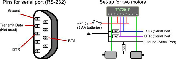
Instead of using the data pins on the serial port, this circuit works on with the DTR and RTS control signals of an RS-232 interface. Unlike the data lines of a serial port, these control signals are high when they’re enabled and can also provide a small amount of current – enough to control a pair of pins on a TA7291P bridge driver.
The rest of the circuit consists of a few resistors and a pair of motors, and the software simply turns the DTR and RTS lines on and off. It’s enough for a small robot to waddle across a table, and given the correct driver is simple enough to mash together out of parts from a junk drawer.


Nobody in the world has a serial port. They were outlawed in 1982 for being so slow and dangerous.
In 1984, apple used serial ports to bring networked printing to the masses.
If you read the first paragraph of the article, he says the project is to control a motor via a USB port using a $4 USB-serial adapter.
It still seems to be a lot of trouble to avoid using a microcomputer– why not use a uC with USB that can control motor speed, perhaps limit the current with switching and feedback instead of piles of parallel resistors, plus you don’t need to worry about timing of python scripts and ajax web accesses.
I guess the answer is that we need better uC development systems so someone can easily plug in a cheap USB-enabled microcomputer. Arduino is easy, but expensive.
We used to worship MacGyver and Rube Goldberg, but today they are thrown under the bus and everyone must do it the right way.
Arduino is expensive? You can get off brand arduinos for $5 each.
” They were outlawed in 1982 for being so slow and dangerous”
Snork…
Hint: Embedded folks have been && will continue using serial ports for the basic reason they are simple. I am an Embedded Systems Engineer. The first thing I get working is a serial port for a Command Line Interpreter (CLI). Good to have a back door for the real work – none of that GUI nonsense.
I think that people will continue using UARTs, but serial ports? Nah.
If only computers still had RS232 ports…
A lot of them do, tucked away on header pins on the mobo. If you’re lucky, you might even find one with a parralel port.
There’s a reason I’m keeping my Thinkpad T61 around for a while…
and my Dell D610, also because it is indestructible. 3 foot drop test video below:
https://www.youtube.com/watch?v=7kk-5cxyuBk
My motherboard is new enough to have PCIe 3.0 slots, but it has two COM ports, a parallel port AND an IrDA port all broken out to headers. From what I’ve noticed, it’s much more common on AMD boards like mine than any Intel equivalent.
Are they serial port or internal USB to serial converter? There is good chances that the second option is true.
Really? I defer to your experience, but isn’t that a pretty pointless way to add that to a motherboard? Even if it’s built into the Southbridge, or whatever they are these days, seems kinda a bizarre thing to add via USB when you’ve got the system bus(ses) available directly.
You can tell by looking at Device manager using the “Devices by connection” option on a windows box.
If they are listed under “PCI Bus”, they are probably from a peripheral chip hanging off the LPC bus these days. (Basically a modern version of ISA bus hanging off a 4-bit 33MHz serial bus. http://en.wikipedia.org/wiki/Low_Pin_Count )
I’ve heard some of the Intel Atom motherboards have parallel ports (and, I’m assuming, serial ports). Last time I looked, they seemed to be pretty popular with the LinuxCNC crowd for this reason. They’re a good source of info on stuff like this since they not only need parallel ports (unless they’re willing to shell out for more expensive dedicated controllers) but they also need those parallel ports to be implemented correctly (meaning high reliability/stability and low latency). Even many systems that have parallel ports have them tacked on and not build as a core part of the system bus meaning that they have high and very inconsistent latency (this is, supposedly, especially true for many laptops).
Those Atom boards are popular because they have low latency. That and with the small form factor they’re easy to put into a control panel. Laptops have crap latency because of their power saving features. People serious about CNC do not use parallel port interfaces. They use I/O boards like these
http://www.mesanet.com/fpgacardinfo.html
Indeed they do! I have a small Atom based linux server at home with 7 COM port headers!
Bought a new asus AM3+ motherboard in november 2011. Has full RS232 and parallel ports on rear. Its current replacement has header pins instead but still possesses the functionality.
Even if your computer doesn’t have serial ports, if it has a PCI slot or a PCI-e slot or a micro-PCI-e slot, then you can get a board for cheap with a fully-supported, real hardware serial port.
The card solution is really cheap and you if you fry it you usually just free the card. I have often wondered with all the cheap serial and printer port cards I see why more people are not using them for projects.
You’d have to really mess up to fry a serial port. They’re designed for something like +/- 15v.
It’s February in snow country, if you don’t have your humidifier cranked up, you can fry a serial port by just touching it (voice of experience).
Indeed. Comms ICs are popular replacements where I work.
That will also fry literally any other communications port.
I just built a new quad core athlon last week and it has a serial port and parallel port on the motherboard.
The described pinout is wrong
1: DCD
2: RX
3: TX
4: DTR ***
5: GND ***
6: DSR
7: RTS ***
8: CTS
9: RI
The *** indicates the pins you want to use.
In other hacks, you can get about 3..4 mA out of these pins.
You can cheat and use TxD if you are running low on output pins. By using a “Line Break”, you can force a “logical 0” on TxD.
FYI: “RS” = Recommended Standard. It has *long* been a proper standard. The name “RS-232” was so 1962. Start calling it EIA232 and TIA232 already.
http://en.wikipedia.org/wiki/RS-232
(accidentally hit “report comment” – oops)
RS vs EIA: I am an old curmudgeon so I will continue to call it RS232, RS422, RS485.
Just like I use DB9 and DB25 which are not correct, at least for one of them. Deal with it. The people I talk to about them understand and that is the critical part.
DB25 is correct, the smaller one is actually a DE9. Although everyone except Rainman knows what you mean if you say DB9
If it’s obsolete anyway you may as well use the term everybody knows. A bit late to start repainting the Titanic.
You are correct about the line break, although there are two issues:
1. RS levels are not TTL levels. A TTL one = 5v (the idle state for TX), and .LT. -3v for the RS level (-6v is typical). The TTL zero = gnd, and .GT. 3v for RS level (typical = 6v)
2. the line break logically emits a TTL 0 for the data biits. You will actually get 9 bits low, including the stop bit (assumes no parity & 8-bit data). You will get a following one or two stop bits, which are TTL ones. Thus, you basically get, for one byte, a duty cycle of 9/10 or 9/11
Note using the TX line you can hack a PWM output.
3. you would need to continually send the line break instead of setting DTR or RTS once to change their states.
#1: I specifically used the “RS232” term “logical 0″ to signify whether the signal is asserted, not the actual voltage level or logic family. It is even used in that “RS232” wiki link.
Neither are the other handshake lines you pointed out as TTL levels. So not even sure what points you are trying to make here except that you are unfamiliar with the subject.
Hint: “Line break” is not a real character. It is a condition when the TxD line is held low for longer than one “word time”. Hence I specifically said “By using a Line Break” instead of the word “sending”.
http://byterunner.com/16550.html
LCR BIT 6: (LINE CONTROL REGISTER (LCR) )
Break control bit. It causes a break condition to be transmitted (the TX is forced to low state) when set to 1.
You set that bit on the UART (or equivalent in USB or OS call) and the TxD line is set to “logical 0” until you reset that bit in the register. So in the host, you can treat it as a output port pin.
Your #2 and #3 assertions are incorrect.
Hopefully someone else would learn something from this.
I know normal RS232 very well – nothing I said about voltage levels was wrong. Quiescent (non-assert) TX TTL is VCC (5/3.3); asserted is gnd. RS232 de-asserted is .lt. -3v and asserted is .gt. 3v. This is the reason the original hack works (assuming you use the right pins).
I have actually never used a line break. I did make an assumption, which you caught. So, I got #3 wrong. Thank you for the correction.
Now, one CAN use the TX as a PWM signal, with the caveat that you will have one low bit and 1..2 (actually 1, 1.5, or 2 bits) high for the time period – assuming you continually send characters. Depending on the receiving device, the duty cycle is #times_high / #total time, ie 50% duty cycle is half of the time high, half low. The receiving device *might* assume all of the high time is first in the period, maybe not.
My #2 is wrong for line break – you are correct. However, if you send a 0x00 byte it is true – again, I don’t use line break. You would need to continually send the desired character.
Note that RS232 bit order is: …
Handshake lines:
The handshake lines, if used, are at RS232 levels because (by default on systems) they go thru a level shifter, ie a MAX3237 or MAX3241 or similar chip.
If you are building a system and want two boards to exchange data, you can use a UART on both and keep the TTL-level signals. We did this on an E1 clock sync box to allow boards to communicate over the backplane.
If you read the RS232 IEEE spec, circa 1996 [rev D] (when I lived with it for several weeks), the handshake and data names apply to the CONNECTION not the PINS, because you are connecting a DTE and DCE ftp://ftp1.digi.com/support/cabling/dte_vs_dce.pdf (quote below)
“This is one of the most misunderstood areas of RS-232. DTE stands for Data Terminal Equipment, and DCE stands for Data Communications Equipment. DTE is typically either a dumb terminal or the serial port on a computer/workstation. DCE is typically a modem, DSU/CSU, or other piece of data communications equipment, hence the names. This is all most people really need to know about these terms.
Where it gets confusing is when you start to talk about signal definitions and direction. For example, it’s easy for someone to understand that when you transmit data, you send it out. However, when you talk in terms of DCE, it becomes an input signal. This is because the specification was written from the perspective of the DTE end of the link. Another example is the Receive Data signal is an input to DTE, but an output from DCE.”
Note the standard PC serial port is DTE. The easiest way to tell which pin on a port or cable, assuming DB9 – oops DE9 – is to know pin 5 is ground. Use a meter with the minus lead on pin 5. The pin 2 or 3 with voltage is TX (if quiescent, will be around -6v) – most useful when looking at a cable to determine if the cable is straight-thru or cross-over.
I got yelled at a few weeks ago for suggesting the jacks have been largely deprecated, despite the fact that very few, if any recent computers have this port. My 2009 Dell Precision lacks them.
I think a USB->RS 232 FTDI cable would do fine. But an FTDI cable costs as much as some USB-enabled microcontroller boards.
Peachy Printer forgoes a microcontroller and uses the analog audio jacks, to save all of a buck or two more needed to place a uC on the board.
any computer with expansion slots can take a serial port card
“an FTDI cable costs as much as some USB-enabled microcontroller boards.”
if you look on ebay or dealextreme, you can find ftdi cables or adapters for about $5.00 or maybe even less.
Bear in mind some (many?) of the FTDI cables do not honour the handshaking signals used in the hack above…
No USB is timed right either.
Be wary of those kind of serial port cards depending on what you want to do with it. For example, the guys in the LinuxCNC community (who rely on parallel ports, not serial ports, but the same kind of issue may apply) have found that even system that have parallel ports installed by default aren’t always capable of supporting their needs. Some parallel ports (seemingly mostly laptops and newer systems where the port was tacked on instead of being part of the core bus design) don’t provide the low latency and/or consistent latency values they need for highly responsive control of their stepper motors.
“if you look on ebay or dealextreme, you can find ftdi cables or adapters for about $5.00 or maybe even less.”
That’s the thing, I think you can get microcontroller boards for similar cost. Adafruit Trinkets run $8.00, a Chinese cloner wouldn’t have to do much to go under $5 each.
I have bought many (Chinese) adapters for about $2.99 on ebay. I think they use prolific chips. They seem to work fine for me.
I bought about 30 of the Pl2303 chips for a total little over $3 with free shipping. I thought ~$0.1 per chip was a typo. :) It takes me less than 15 seconds to desolder/recover those packages, so it was a risk worth taking.
Out of 4 chips I tried, 3 of them works fine as is with latest drivers for Win7 x64. That 4th one would probably work with older uncrippled driver or libusb. I can see its usb info, but the driver knew it was a “fake” part.
I built a USB-Serial converter with an old Dell desktop +/-12V GD75232 chip (powered by a beefy external switcher) for my old programming dongles.
I am planning to use one to as a bitbang SPI to drive a 74HC54 for more output pins!
“I think a USB->RS 232 FTDI cable would do fine.”
Not really. Those kind of controllers are almost always designed for very limited use-cases. The differences between between how USB and RS-232 work mean that developing a converter that is stable beyond extremely short bursts of info is extremely difficult. Most adapters don’t bother trying, meaning that any attempts at stable long-term connections (more than maybe a few seconds to a few minutes) will break in the middle of communications.
The testing lab I used to work at ran into this problem while trying to use USB-to-RS232 adapters to connect to the previous generation of RS-232 only data acquisition units for high channel count measurement of heat values over extended test periods (hours, days, weeks, etc.). We ended up having to do a lot of comparative testing and found that the only unit that could handle even a moderately long-term stable connection was the USB-to-RS232 adapter from National Instruments (which makes sense since they sell data acquisition hardware). Unfortunately, as can be expected, those units don’t come cheap.
The problem with USB/serial adapters is the USB protocol itself. This is a polled protocol. Any usb device can’t send data to host computer until asked for. So if your application stream serial data to usb/serial dongle this one will buffer it and transmit data when polled by host PC. This imply delay and possible buffer overun in the dongle if there is no hardware handshake between the appliation board and the dongle. USB host polling interval may be as much as 1msec ore even more. Not good for realtime application.
I have had excellent results using the USB-RS232-DB9 from Accesio – best $40 I ever spent on a cable.
The modern day chips have 128 bytes (or 256 or even more) of data for each of the 1ms or so between USB poll. So you are looking at 128×10 bit/1ms = 1.28Mbps ballpark which still *should* work fine in theory.
More likely those pesky power management would shut down the hub or the chip and the level shifter if they have been idling for a while. They probably don’t wake up in time to catch the next burst of data. Or it could be firmware and/or driver bugs etc.
An example of a modern computer that has the rs232 is the Dell OptiPlex 7010
We use them with some custom hardware that doesn’t seem to like the USB Adapters.
Its really odd though. Dell doesn’t seem to care to include that in their list of features. although they also don’t list the Ultra small form factors that we use either. I know HP also has a series of PCs that have it as well
I do appreciate machines that still have serial ports – and yes, sometimes they are only available as headers on the mobo, but they are still there! Also, some docking stations have real serial ports (not USB dongles). I still have plenty of serial-connection hardware and *use* my serial ports for data.
Ahhhh, I remember buying a 16550 serial card. An ISA card! To plug my 200 quid 28k modem into. Lasted long enough before broadband came to be worth the money.
rats, thought the Arduino shield would do the trick, but no hardware handshaking that doesn’t use the digital pins to source, meaning….what’s the point.
If you have a serial port, you have a microcontroller or even a computer on the other side…. There’s no such thing as driving without a microcontroller :)
Well… a microprocessor is more likely if you’re using a laptop or desktop. But I get your point.
That was the “computer” part. But I get your point ;-)
the argument that parallel or serial does not exist on a brand new state of the art computer is moot.
if you only own one computer, you arent quailified for the job.
if i owned a company i would only hire people that walk through the door with
THREE laptops.
fast dualboot (XP or newer / linux)
old dualboot (win9x / oldlinux)
and ancient dualboot (dos / win31 / veryoldlinux)
why? cuz he can get the job done in 3 minutes including booting up.
that saves the boss hours of him installing virtual operating systems andor allowing them to use port from within VM.
… or fiddling with drivers only to find out the three USB-serial converters he has are not compatible with robot XYZ.
when the 1million$ robot was created, they assumed that the owner would have five (freaking) dollars spare for a used laptop to upload the new design file.
only boring consumer software is guarenteed to use the serial port in a standard way.
everything else needs direct, hardware registers.
PS: my desktop computer has hardware serial and it is dualcore. my ram is measured in GIGAbytes, yet i can signal to the outside word. LED if you will.
stop FINANCING the end, buy one with serial!
PPS: you could always BUILD ONE…
if you use sata diskdrives(CD/DVD/ect) then you have free IDE cable!
if your not looking for RS232 and only want direct parallel then throw a few logic chips at your IDE/PATA port and tell windows it is a standard LPT port.
then you can open avrdude and tell it your using parallel at IDE address.
Lucky for us you don’t own a company then. And lucky for you as you couldn’t get anyone to hire anyway ;)
But seriously: for many people having more than one computer is a problem so the decreasing number of machines with serial ports is a real trouble.
For desktop machines it’s still relatively easy to add ports via expansion cards and, as you point out, will most likely support at least one ATA port.
Notebook/laptop computers is much harder to do hardware hacking with. ATA was dropped ages ago, Expresscard slots are reserved for mobile workstations and even usable internal PCI express minicard slots are almost non-existant. If one can live without WLAN support it could be possible to hack a Expresscard serial card into that slot, IFF one can find a true PCI express -> serial bridge Expresscard and not a (the usual case) USB->serial one.
USB->serial sometimes works, many times not. USB->parallel almost certainly will not work for anything.
There is one chance that one could tap into the LPC (low pin count bus – a shrunken ISA bus) and wire a super-IO chip into it. But that’s a slim one.
Actually, I was thinking of laptops. I rarely buy desktop machines anymore. And I have at least 5 laptops. No matter how old they are, I can’t let go of them…
Remember Covox LPT “Sound Card”
http://en.wikipedia.org/wiki/Covox_Speech_Thing
http://upload.wikimedia.org/wikipedia/commons/8/8d/Covox-Stecker.svg
No ports?
I’m here on my lunch break at work. My workstation is this little Dell thingy about the size of a three-ring binder and only a couple of years old. It clearly has a serial port sticking out the back.
Maybe things have changed in 2 years? I just did some random clicking on motherboards on newegg.com. Sure enough.. no serial ports. But… they do still have PCI and PCIE slots. It really isn’t that hard or expensive to add a serial port or ten. Actually… it isn’t hard to add parallel ports… 8 inputs, 8 outputs as well as a number of control lines. It’s almost like a whole Arduino built into your computer!
Better yet, you don’t have to check each time you plug in if it’s TTYUSB0, TTYUSB1… TTYUSB9352. It’s always the same every time! You don’t even have to fool around with udev to make it stick to one port, (and do it all over again every time you update udev and the config files get overwritten or the format for them changes).
USB just doesn’t seem ready for real world use to me when you have to go into /dev (or the device manager) find the device number and update it in some software preference every time you re-plug a device in. And that’s for attended use. If you want to set something up that is automated USB is pretty much worthless!
The device names might stick if the dongles have unique onchip serial# or *optional* external EEPROM *soldered in* and their drivers to make use of them.
Otherwise, it is a wack a mole device naming game.
There’s nothing wrong with taking apart and soldering directly to a USB serial adapter if that is all you are ever going to use it for I guess. It’s kind of presented as the only option though. A quick look at Ebay finds 10 packs of DB9s going for less than $2! I didn’t even browse much to be sure there weren’t better deals nor did I look for a single connector price.
You could just get a bunch of connectors, solder them to however many projects and then keep re-using that USB to serial converter by just plugging it in. As a bonus, you could switch which project your serial convert is plugged into without disturbing the USB side of the connection. That way your device number doesn’t have to change all the time.
interresting ide, i like the simplicity. If you need a h-bridge to drive a motor some day, , i have a free H-bridge pcb with atmega328 (arduino) on the pcb. Now it is used as a power inverter, but if you like, you can easy write a sketch for motor controll
http://en.techmind.dk/arduino/inverter-12-volt-to-230-volt-with-arduino/
Ha-ha “new guys”, I mean anyone who hasn’t been involved in electronics for 20 years or more. Always trying to kill off a communication or connection standard because their new PC doesn’t think it needs it anymore. LONG LIVE THE SERIAL PORT!!! I’ve built several high end PC’s in the last several years and every single one has a serial port. Maybe not on the connector panel, but on a header at least. Most widgets take that fancy PITA to use, licensed, pay to play USB connector and dumb it down to 9600 serial via a UART. If you were taking to a real RS232 line, you could probably even get away without using a level converter even (as with PICs). USB is great and fast for external drives and such, but most things don’t need the speed and expense to implement it.
Ive actually thought of this myself. The reason is that multi-port PCI-E serial port boards are cheap and readily available. In fact, you could even use dirt cheap dual port boards, either two or three in spare slots,or get one of those 1-4 pci bridges that the bitcoin miners use and connect them through those. There are tons of different options. And its connected directly to the PCI Express buss. (The reason that you dont want to typically control motors over USB is that the latency is variable.)
I never looked deep enough to see if it would work but the idea was, you have RTS and DTR as outputs on a standard serial port. RTS would be connected to the enable line of a stepper controller IC. DTR would control the direction. The transmit data line would be your step line. It would need a level translator of course. When the line is idle, its in the 0 state. So you just manipulate the data and the baud rate to send your step pulses. If you want a single step pulse, you just send 0xFF at the appropriate baud rate to make the pulse as long as you need it. You also have digital inputs. There is CD,CTS, DSR and RI. (Four digital inputs per serial channel.) Two of those could be used for a quadrature shaft encoder.